4

This is my first post in this stack group, so please forgive me for any shortcomings of my question.

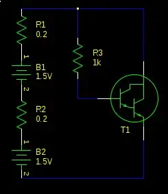
I'm designing a circuit for a high side switch of around 60V DC (battery). Attached is a sketch of the circuit I have so far. VBat is around 60V, the switch here is a voltage controlled switch, switching for 2 seconds - in real life it will be a simple "hand controlled" momentary switch. R7 represents the load (which will be a voltage regulator in the end).

When simulated the circuit seems to work, but I don't know if this approach is reasonable.

My three main questions are:

  • The voltage divider R1 / R2 brings the 60V down to 10V, because most momentary switches seem to be built for 12V. That's why i choose R1 / R2 to be so high, to get the constant leakage current down as much as possible. Do I have to fear any antenna, or other undesired effects with such high resistances?
  • Is there a better approach, without leakage current, to use 12V switches?
  • Is there maybe a better approach in general?

Just to be on the same page, here is a short description of what the circuit should do: As long as somebody presses (and holds) the momentary switch (voltage regulated in the schematic just for simulation) the load, represented by R7, should be switched to 60V on the high side. Later the load will be a voltage regulator that ouputs 5V to power a micro controller and some leds. That's why I was thinking about a high side switch, to have the same ground for all components.

schematic

simulate this circuit – Schematic created using CircuitLab

wschopohl
  • 141
  • 3
  • 1
    Connect SW4 over R2 and the base to the middle of R1 & R2. – Mats Karlsson Nov 04 '20 at 14:33
  • i.e. don't leave inputs floating subject to stray interference from very high impedance and low current noise. – Tony Stewart EE75 Nov 04 '20 at 14:35
  • you mean short the base of q1 to ground with a resistor? – wschopohl Nov 04 '20 at 14:36
  • No. Keep bias on Vbe to gnd at all times with pullup, then shunt base to ground .. You can always use BC846BLT3G NPN 65V on low side then mechanical switch Vbe//Load*20 to pullup x5 Rbe for 60V – Tony Stewart EE75 Nov 04 '20 at 14:44
  • The high resistor values in that voltage divider will only provide around 5.6uA into Q1's base. That doesn't seem like it would be anywhere near enough current to make Q1 pull R6 low enough to turn M1 on. – brhans Nov 04 '20 at 14:45
  • What's your load? A motor? – winny Nov 04 '20 at 15:03
  • The load is a voltage regulator with 5V output, that will power a uC and some led's. That's why I want a high side switch, to have the same ground for all components. – wschopohl Nov 04 '20 at 15:06
  • @brhans: according to simulation the current to Q1 base seems to be enough. the values of the transistor are from this type: https://docs.rs-online.com/0b05/0900766b8121b520.pdf – wschopohl Nov 04 '20 at 15:20
  • @MatsKarlsson is the rearrangement of the switch, that you talked about, like in the answer of Tony Stewart below? – wschopohl Nov 04 '20 at 15:26
  • 3
    If the load is only a separate 5V regulator, you might try looking for a regulator that has an output enable pin. It's a reasonably common feature, and that would (probably) be usable with a low-voltage switch. – W5VO Nov 04 '20 at 15:28
  • _most momentary switches seem to be built for 12V_ is very shaky reasoning to choose your base bias network. I think some learning about bipolar junction transistors is needed. The On Semi MMBTA06L has a VBE(ON) of only 1.2 Vdc max. – Reinderien Nov 04 '20 at 16:10
  • So nearly all switches I found are either built for 12V or 24V. There are only very odd ones to switch the 60V directly. That's why I want a circuit that safely uses a 12V variant. What exactly are you suggesting regarding the NPN? My understanding is, that it turns on above 1.2 V , the maximum Vbe being 80V. In my case it would be around 10 V .. ? – wschopohl Nov 04 '20 at 16:23
  • Of interest to you should be figures 7-9 in https://www.onsemi.com/pub/Collateral/MMBTA05LT1-D.PDF . BJTs are not voltage-driven, but current-driven at the base. If you want a voltage-driven device, replace it with a FET. – Reinderien Nov 04 '20 at 16:48

2 Answers2

5

You need to back up your thinking about five steps. It should not be

  • I need to cut off the input to a regulator, so
  • I need a high-side switch, so
  • I need to convert from a low-side switch

Instead, it should be

  • I need to disable a regulator, so
  • I need a regulator with an enable line.

The simplest case is something like a ZXTR1005K4 with 100Vdc in max, 5Vdc out fixed, and your pushbutton going to the enable line. This doesn't take into account that - if I were to make a highly dubious guess that your regulator input current is 60V/400R = 150mA, this would exceed the current rating of this device and you'd have to shop around a little more.

The even simpler thing to do is revise your idea that it's hard to get a 60V-capable pushbutton, and simply put it in the input path of a fixed regulator with no enable. There are many off-mom switches that satisfy your criteria.

Reinderien
  • 3,102
  • 16
  • 28
  • "Should" implies an unnecessary authoritative directive. The designer may choose either a 1) high side or a 2) low side switch primary switch or an 3) enable line or a 4) secondary switch, depending on other considerations not given, such as Off current limit, On current limit, cost but a floating input is the only critical fault , susceptible to stray noise and false trigger when off. – Tony Stewart EE75 Nov 05 '20 at 08:21
-1

Better way

schematic

simulate this circuit – Schematic created using CircuitLab

Down side is R102 uses 700 mW and must be rated for >=1W

Keep a logical loop as physically small area as possible ( twisted pair) to minimize a loop antenna effects. Add RF Cap to Vbe for AM or arc noise interference suppression >100kHz >> 20 dB eg 1 kHz

Tony Stewart EE75
  • 1
  • 3
  • 54
  • 182