5

enter image description here

What is the value of Vout if we know the value of Vin in this case?


It is a buffer amplifier, but it has two extra resistors so I think that the gain is smaller than 1, but how small?


(Vin-V3)/R1=0 <=> Vin-V3=0 => Vin=V2=V3

(Vout-V2)/R2=0 <=> Vout-V2=0 => Vout=Vin=V2=V3

Cristi
  • 677
  • 2
  • 9
  • 21

2 Answers2

7

With the ideal opamp, we cam assume:

  • infinite gain
  • infinite input impedance
  • zero offset voltage

So, whatever we input to the positive (or negative) input is multiplied by infinite gain. If we leave the opamp open loop, the output will just hit one of the rails (positive or negative depending on the polarity of the input signal)

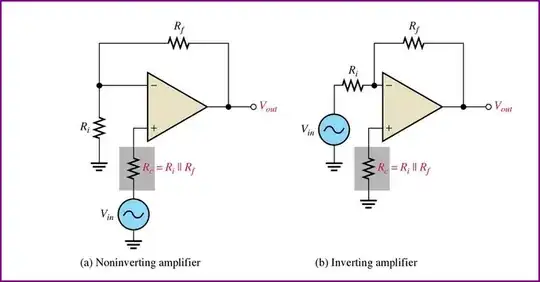
However, if we feed some of the output back to the inverting input, we can use this to control the gain (and negative feedback has some other useful effects also)

With your example and an ideal opamp, it doesn't matter what value the resistors are, or whether they are equal. Since there is no current flowing through either of them, the result is always the same (a gain of 1).

With a real opamp, you have an input bias current (we will ignore the myriad of other non-ideal parameters and just focus on this one), so matching the impedance both inputs see is a good idea (unless there is already internal compensation, which some opamps have - in some cases matching the impedances can make things worse due to the input bias currents being unequal)

So for the example in your question, say we have an input impedance of 1MΩ (a very low value, but some opamps can have very low input impedances, make sure to check the datasheet), we use 10kΩ for the input resistor, but no resistor in the feedback loop. We will choose an input voltage of 1V.

We now get an input current of 1V / 1MΩ = 1uA.

So we now have a voltage drop across the input resistor of 1uA * 10kΩ = 10mV, which is present at the output (which will be 990mV) instead of 1V

If we want to prevent this, we need to match the voltage drop in the feedback loop to cancel out the offset caused by the input bias currents. So we use 10kΩ for the feedback resistor, it drops 10mV too so output is now 1V again.

Here's an example of matching the parallel combination of the feedback resistors when you have some gain:

Opamp Bias Current Compensation

This app note from Analog Devices is worth a read for more in depth discussion.

Oli Glaser
  • 54,990
  • 3
  • 76
  • 147
  • 3
    +1 for explaining why R2=R1 matters in the presence of input bias currents. @Cristi : read that bit carefully! –  Jan 05 '13 at 22:59
4

For an ideal op-amp, the following analysis holds. For a practical answer you will need to simulate your circuit using something like LTSpice.

(Input - V3) / R1 = 0, (op-amps have infinite input impedance)

(Output - V2) / R2 = 0, (op-amps have infinite input impedance)

V2 = V3 (op-amps work to mantain Zero potential difference between their inputs when configured for negative feedback is in this circuit)

I have explained the important aspects of an op-amp for solving this problem. I leave the substitution and result for you to find.

placeholder
  • 29,982
  • 10
  • 63
  • 110
NickHalden
  • 4,167
  • 3
  • 31
  • 40
  • 2
    Bingo. Notice that would not be the case if R1 != R2. – NickHalden Jan 05 '13 at 12:42
  • That's good to know! But what changes if R1 != R2 ? – Cristi Jan 05 '13 at 12:48
  • ...Look at the equations I wrote. I left them in terms of R1 and R2 specifically so I would not have to answer that question. – NickHalden Jan 05 '13 at 12:50
  • Assuming R1>0 and R2>0, the result is the same for any values of R1 and R2, because: (Vin-V3)/R1=0 <=> Vin-V3=0 (R1 changes nothing). Same thing for the second relation... – Cristi Jan 05 '13 at 12:56
  • 1
    Ugh, right you are. I can't think straight right now. – NickHalden Jan 05 '13 at 12:59
  • The point of this problem is finding out if there is negative feedback, in which case that thing behaves as a buffer. Stating V2=V3 is not always true, even for ideal op amps. – Vladimir Cravero Jan 05 '13 at 13:28
  • 3
    No, opamps do NOT "*work to maintain 0 potential difference between their inputs*". All they do is multiply the difference between the two inputs times a large value at put that on the output. In some circuits, feedback may be employed for the result you state, but getting that behavior is not inherent to the opamp itself. There are plenty of opamp circuits where your statement is not true. – Olin Lathrop Jan 05 '13 at 14:03
  • About the negative feedback thing, that is the hypothesis that leads to the zero volt difference between in+ and in-, there is a nice theorem called "Pellegrini's theorem" that is not known worldwide and provides a way to analyze reaction in any circuit. – Vladimir Cravero Jan 06 '13 at 21:15
  • 1
    @OlinLathrop This is a pretty standard way to teach op-amps with the requirement that it is in a negative feedback configuration. – Kortuk Jan 07 '13 at 16:13
  • 2
    @Kortuk: There a lot of bad ways to teach electronics, and some of them are common. The problem is that too many will just follow the "rule", not think about what the circuit is really doing, and forget whatever constraints may have been mentioned along with the rule to make it valid. I have seen people get this wrong often. – Olin Lathrop Jan 07 '13 at 17:43
  • @OlinLathrop Ohh, I agree that the condition should be there, but with less work then writing a comment you can just edit it! Fix the post and put in a comment, "I changed this because many people forget". I agree a more ideal is teaching how those conditions are generated, but I thought I might suggest the edit method as you are our most active user that will cause a much more direct improvement to the site. – Kortuk Jan 07 '13 at 18:13
  • @OlinLathrop On an actual content related note, thanks for pointing out my misunderstanding. The rest probably could've been left unsaid. – NickHalden Jan 07 '13 at 21:30