0

I have designed an amplifier circuit using my limited knowledge about transistors. Here is what I've got. The input is from a audio jack from my cellphone. The frequency response is at about 1kHz as you can see with the 160uF cap on the preamp. I want an output of about 20 - 30W so with 12V 2,5A.

2n2222A and 2n3055 Amplifier circuit

I want all the parts so that I don't have to go twice to the store. Please give your feedback on this circuit. I have also played with small low output power BJT amplifiers "pre amps" like the BC327-40 or BC237 and I noticed something when I make a voltage divider to bias the transistor the measured bias voltage is less forward bias than intended or calculated. When I make a voltage divider without anything else on it the voltage reading is right.

Does anyone know what's going on?

Transistor
  • 168,990
  • 12
  • 186
  • 385
Gideon
  • 5
  • 3
  • 3
    *Is my Amplifier circuit any good?* no, it's pretty poor and will distort badly but may be good enough for what you want to use it for. But who can tell because you haven't defined what your expectations are for gain, distortion, frequency response and input impedance and, you'll also have a good chunk of DC current flowing in the speaker (a bad thing for decent speakers and who cares for crappy speakers). – Andy aka Oct 30 '20 at 14:26
  • 2
    Or, to put this more neutral: It's hard to say whether something is good without knowing what it's used for. A dull knife might be an excellent tool to apply a smooth layer of e.g. cake frosting. – Marcus Müller Oct 30 '20 at 14:29
  • 1
    To the second question, you aren't accounting for the base current in your divider calculations. –  Oct 30 '20 at 14:29
  • I have edited Quis to explain better for what it is intended for. – Gideon Oct 30 '20 at 14:35
  • @Gideon Audio is a AC signal, so a "good" amplifier should be able to drive the speaker in both polarities. Your desired output power is also unrealistic. Theoretical maximum RMS output power with a 12V supply and a 4 ohm speaker is 4.5W (18W bridged). – Unimportant Oct 30 '20 at 15:29
  • @Gideon An emitter follower won't drive a speaker well. In general, speakers do not appreciate a *continual DC current* and you otherwise won't be able to operate the speaker properly. And at 20-30 W? Not even close. You need a different topology, entirely. – jonk Oct 30 '20 at 20:33

5 Answers5

3

Bird's Eye View of Single-Ended and Bridge-Tied Output Loads

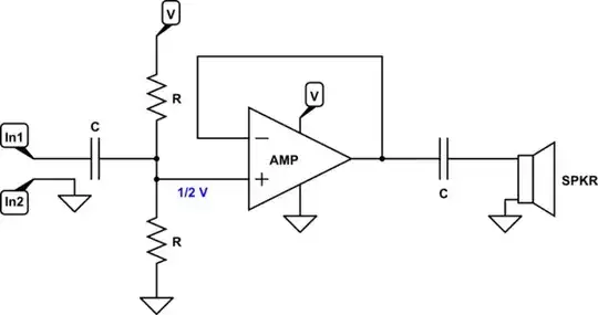
Start with the speaker itself and assume at first that you have access to a bipolar power supply rails, such as \$\pm12\:\text{V}\$. Let's also assume that you have a ground-referenced input signal. Then there are two basic arrangements:

schematic

simulate this circuit – Schematic created using CircuitLab

(Keep in mind that it is possible to also use an audio transformer to match up the load, better. So the speaker, as shown, could be replaced by the primary of an audio transformer with the speaker hooked up to the secondary.)

I'm showing everything hooked up as DC connections, above, and the AMP is assumed to have some possible voltage gain, as well. There is a lot buried inside the AMP.

If the input is at \$0\:\text{V}\$ then the output will also be \$0\:\text{V}\$, for both the single-ended and the bridge-tied load arrangements.

The inverter shown for the bridge-tied load arrangement is designed to mirror the voltage across the ground reference, so that if \$\text{IN}_1=+10\:\text{mV}\$ then the inverter output will be \$-10\:\text{mV}\$. (I used "180" on the symbol to suggest the idea of \$180^\circ\$ phase relationship between its input and output.)

In the single-ended case, the bipolar rail voltages for the amplifier must be \$V=\sqrt{2\cdot R\cdot P}\$, where \$P\$ is the desired maximum power output, \$R\$ is the speaker impedance, and \$V\$ is the magnitude of each of the two bipolar rails. You must pad \$V\$ a little bit to account for the control overhead voltage, which is typically on the order of about \$1\:\text{V}\to 2\:\text{V}\$ for each rail.

For example, if you have \$R=8\:\Omega\$ and \$P=1\:\text{W}\$ then expect \$V=\sqrt{2\cdot 8\:\Omega\cdot 1\:\text{W}}=4\:\text{V}\$. Given the lower end of about \$1\:\text{V}\$ overhead, this would suggest bipolar power supply rails of \$\pm 5\:\text{V}\$.

There is a huge advantage for the bridge-tied load. In this case, you'd only need one of the rails -- namely, \$+5\:\text{V}\$. So you save yourself an entire voltage rail! Take a look at the TDA8551: 1 W BTL audio amplifier with digital volume control datasheet for an example proving exactly this result. Here all you need is a single supply rail of \$5\:\text{V}\$ in order to deliver \$1\:\text{W}\$ into a speaker load of \$8\:\Omega\$! (They achieve this by allowing each amplifier to go into gentle saturation as they approach their rails, without significant distortion.)

The problem with bridge-tied loads (BTL), of course, is that they require two amplifiers. Not just one. (And an analog inverter.)

Single-Supply Rail Case

Let's assume you aren't in a position to create two amplifiers (plus an inverter) in order to get the most out of a single supply rail. But that you are stuck with a single supply rail.

Here, you can make an adjustment to the earlier diagram:

schematic

simulate this circuit

Here, if both \$R\$ values are the same, then the midpoint is half-way between the supply voltage and ground. Now, the amplifier output will also be, nominally, half-way between the supply voltage and ground. The two capacitors will charge up to the difference, quickly, adding just enough voltage on both ends of the system so that the quiescent state will be just fine and there will be no current in the speaker without an input signal change.

We are still limited by the need for a \$1\:\text{V}\to 2\:\text{V}\$ voltage overhead. But at least we can operate the system now with a single voltage rail.

Let's assume your \$R=4\:\Omega\$ and \$V=12\:\text{V}\$. In this case, we find that \$2\:\text{W} \le P\le 3.125\:\text{W}\$, after subtracting the voltage overhead range. This won't be between your hope of \$20\:\text{W}\to 30\:\text{W}\$. But it's something.

Jump Right In

With BJTs, you may consider about \$2\:\text{V}\$ of voltage headroom. This leaves about \$12\:\text{V}-2\cdot 2\:\text{V}=8\:\text{V}_\text{PP}\$ or \$4\:\text{V}_\text{PK}\$. From that, we can estimate a maximum of about \$\frac{\left(4\:\text{V}_\text{PK}\right)^2}{2\;\cdot\; 4\:\Omega}=2\:\text{W}\$ into your \$4\:\Omega\$ speaker. I don't think you can expect more than this from your \$12\:\text{V}\$ rail voltage.

It's pretty easy to see that your peak current will be \$1\:\text{A}_\text{PK}\$. At that current, you cannot just use a small-signal BJT. In fact, you probably will require at least two BJTs for each quadrant. So your output stage will have four BJTs in it.

(We could do better with a bridge-tied load. But that's a lot more work.)

You can use either Sziklai or Darlington pairs for this. I'd recommend Sziklai, to help reduce the overhead voltage required. (In fact, you must use Sziklai if you want to keep the overhead voltage to around \$2\:\text{V}\$ at each margin.) So I think it's a requirement for Sziklai, in this case.

In general, something like this:

schematic

simulate this circuit

There's a need here for a special voltage difference (\$V_\text{SPAN}\$) which can be a \$V_\text{BE}\$-multiplier construction. If so, there will be a need for a current source to feed it, as well.

For the output, there may need to be a Zobel network (not shown.) But that can also be deferred until later.

That said, the basic idea for the 2-quadrant driver is represented above. And it provides a starting point for designing the rest. And now you can also easily see why there is some overhead voltage required, too.

I've made some points, now. I think you can now see that there is more required, than the approach you provided. These details are important. You've also now (hopefully) realize that with a \$12\:\text{V}\$ single-rail supply you can only expect about \$2\:\text{W}\$ (and likely no more than \$2.5\:\text{W}\$ unless you go to some extreme measures) into a \$4\:\Omega\$ speaker. This is simply because you have to take into account the overhead voltages required, both on the near-ground side as well as the near-\$V_\text{CC}\$ side, for controlling the output. With only a \$12\:\text{V}\$ single-rail supply, these subtractions really hurt a lot as they are a significant part of the total supply range.

I'm tired at this point. It's enough to make the case that you cannot expect much more than about \$2\:\text{W}\$ into a \$4\:\Omega\$ speaker with a single \$12\:\text{V}\$ supply, unless you use a bridge-tied arrangement (which is more than twice as complex to develop.)

jonk
  • 77,059
  • 6
  • 73
  • 185
1

I want an output of about 20 - 30W so with 12V 2,5A.

You might get that with a resistor across the 12 volt supply but not driving a semi-distorted sinewave into a 4 ohm load from 12 volts. The highest magnitude sine waveform you can get from this circuit is about 11 volts p-p. That is an RMS voltage of 3.89 volts and that is a power of 3.89² / 4 ohms = 3.78 watts and miles away from 20 watts.

Andy aka
  • 434,556
  • 28
  • 351
  • 777
  • To explain this a bit further, Gideon: 2.5 A is right when your load continuously gets the maximum current. But clearly, a piece of audio cannot mean a constant current through your speaker. – Marcus Müller Oct 30 '20 at 15:10
  • How do you work out the RMS voltage from this circuit? – Gideon Oct 30 '20 at 15:14
  • @Gideon in all honesty, by simulating it in SPICE. – Marcus Müller Oct 30 '20 at 15:14
  • @Gideon do you know what the RMS voltage of a 1 volt sinewave is and how it's calculated? – Andy aka Oct 30 '20 at 15:15
  • @Andyaka No not at all. I will gues its 1 volt RMS? – Gideon Oct 30 '20 at 15:19
  • And what will be the peak voltage of the sinewave? And then what is the peak to peak voltage. Then what is the ratio between p-p and RMS. – Andy aka Oct 30 '20 at 15:22
  • @Andyaka the rms is peak to peak multiplied by 1/ (square root of 2) thus 1v rms is 0.707 v peak and 1.41 V peak to peak. so 12v circuit like mine can only have 12 v peak to peak sine wave thus 6v amplitude and that is 4.24 V RMS. I dont understand how you come from RMS and load to Watt. i have an idea because dc current true the speaker would be with 2,5A and 12V 30 W but I gues with ac that's not the case? – Gideon Oct 30 '20 at 16:15
  • @Gideon well I think that you can only achieve 11 volts p-p hence RMS is 3.89 volts and power is $$\dfrac{V_{RMS}^2}{R}$$ hence power equals 3.78 watts. – Andy aka Oct 30 '20 at 16:53
  • Thanks i have learned something today. So i just want to achieve wat i can with 12v. Is there any changes i can make to make it better? – Gideon Oct 30 '20 at 18:29
  • @Gideon see my answer: replace it with a different type of amplifier. – Marcus Müller Oct 30 '20 at 19:10
  • @Gideon For a class-A design, consider [reading through this](https://electronics.stackexchange.com/a/503581/38098). Not efficient. But at least it is designed to work. If you just want a bird's eye overview about single-supply amplifier choices, [this](https://electronics.stackexchange.com/a/325502/38098) covers the basics in the first few diagrams. A speaker driven in-series with the large, quiescent DC current used in class-A just won't work well. – jonk Oct 30 '20 at 23:45
0

Your design is as far away from a high-efficiency amplifier as it gets.

You're wasting a lot of power through DC current through your speaker. Could probably be solved well with a series capacitor, but that invalidates your biasing

For an acceptable audio quality (that's subjective.. but I don't think you'll be satisfied with what you've built), you'd have to keep your audio amplitudes within a small range so that the lack of linearity of your amplifier doesn't become too dominant. Problem is that this precludes high gain with this circuit.

We don't really know your design constraints. For example, high gain, high-efficiency audio amplifiers for 12 V supply to me sound very much like a case for class-D amplification. But I don't know whether you'd accept a "go out and spend 2€ on a class-D amplifier IC".

Marcus Müller
  • 88,280
  • 5
  • 131
  • 237
0

We learn about the circuit of an audio amplifier before we try to design one.

  1. You NEVER put DC in a speaker because then the DC holds its coil and cone to one side then it cannot swing properly back and forth.
  2. You NEVER bias the base of a transistor with a single resistor to the positive supply because some transistors have high hFE and others have low hFE even if they have the same part number.
  3. The value of a coupling capacitor is calculated, not guessed. Your low value for the 1uF capacitor feeding the 210 ohms base resistor and 2N3055 transistor cuts all sound frequencies below squeaky frequencies.
  4. Your speaker heats with 6W but its output power is almost nothing. You know how smooth and symmetrical a sinewave looks like? Here is a simulation of how the output of your circuit looks like:

enter image description here

Audioguru
  • 3,894
  • 5
  • 8
0

Here is a fairly good but simple power amplifier using nearly as much of the 12V as is possible. It produces 3.25W into 4 ohms but if it is bridged (two of this amplifier, one amplifier for each speaker wire but one of them inverted) then the output power is about 11.4W. I used oddball transistors that are in the simulation program.

Good 12V amplifier

Audioguru
  • 3,894
  • 5
  • 8