1

I have a problem I cannot figure out. I have this circuit which should control two LED strips either by wemos OR (methods are switched between by SPDT because I don't know automatic way) manually. Each "switch" should be able to turn on one or both leds.

Circuit details

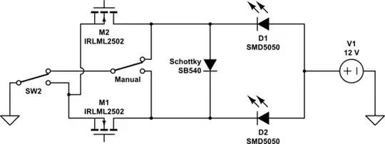
Wemos uses two N-mosfets (irlml2502) to turn on/off leds. Manually I turn them on/off by SPDT switch. Circuit is powered by 12V adapter going to the LEDs and buck-converter to convert to 5V to power wemos. To separate LEDs powering I use Schottky diode SB540.

PROBLEM

The problem is, when I use manual switch, it turns on both of the leds everytime. Also, the buck-converter´s power led is ON on that time but the IN- is not connected to anything.
Even when I connect ground to buck-converter IN- both ledstrips are turned ON.
As I understand it, ground to the mosfets should flow through buck-converter but it is flowing flowing somewhere else.

Only thing I can think of is that MOSFETs are allowing ground to flow "backwards" from drain to source and power the circuit through each other. Could you please help me fix the circuit?

Picture description

  • Circuit is not powered on pictures.
  • Purple colour shows the ground when I want to power single ledstrip.
  • Turquoise should power both strips.
  • Bold black wire upper-right is manual switch 2 and blue is manual switch 1. Curved blue on the right side is ground.
  • In schematics I ignore buck converter and wemos pins output to mosfets. One ledstrip two ledstrips clear circuit wemos buck converter

schematic

simulate this circuit – Schematic created using CircuitLab

GTessa
  • 33
  • 5
  • Do mosfets have pull-downs? what is purpose of sb540 diode? get rid of It and try then (It allows for both leds power at the same time using switch) – fifi_22 Oct 29 '20 at 19:41
  • MOSFETs only have resistors from wemos to gate. Diode SB540 is dividing the circuit so that I can turn on only one led strip D2 or both of them D1+D2. Look at manual switch in schematic. Anyway, I removed diode and it is doing the same. – GTessa Oct 29 '20 at 19:51
  • 2
    Check voltages from Gates to ground – fifi_22 Oct 29 '20 at 19:55
  • 4
    Why not connect the switches (SW2 and Manual) to a GPIO pin of the WeMos and then modify the programming? – Mats Karlsson Oct 29 '20 at 20:02
  • @fifi_22 voltage on one MOSFET is always zero (when using manual switch) and the other one is either 0,3v or 0,7 depending on which manual branch is turned on. – GTessa Oct 29 '20 at 20:25
  • On the Picture with blue lines added I Think that ground of Led stripes is directly connected to ground. Check connections with multimeter – fifi_22 Oct 29 '20 at 20:29
  • @Mats Karlsson what do you mean by connect to GPIO? I want to have a way to switch between wemos control and manual control. But you gave me a really good idea. To have two buttons to turn on one or both led strips and connect them to GPIO. That way I should be able to control it both wemos and manually at once programmatically. Sorry I am a beginner in these things. – GTessa Oct 29 '20 at 20:33
  • @fifi_22 if you mean that blue wire going up on the right side, it is not. Bold black is manual switch 2 and blue is manual switch 1. Curved blue wire on the right side is ground. It is turned off. I will add this explanation into picture description. – GTessa Oct 29 '20 at 20:38
  • @fifi_22 I found out that one MOSFET with voltage between gate and ground has been shortened. I will look at this later if it helps but thanks for your point. – GTessa Oct 29 '20 at 20:52
  • Instead of having a manual control connected to the hardware and overriding the WeMos, connect the switches to a digital pin on the WeMos and define it as a input. Then you can control the functions of the LEDs with the switch via the WeMos. Of course this means that you have to add the code for this functionality to the existing code of the WeMos. – Mats Karlsson Oct 30 '20 at 10:16

1 Answers1

2

There is a logical component "OR" that could be used. What is a logical gate? That is extensivly explained here https://en.wikipedia.org/wiki/Logic_gate

schematic

simulate this circuit – Schematic created using CircuitLab

Another solution is to add the switch to a GPIO on the WeMos and add code, example https://www.arduino.cc/en/Tutorial/BuiltInExamples/Button and if it is a push button please add some "debouncing" code as well, ref. https://www.arduino.cc/en/Tutorial/BuiltInExamples/Debounce

The debounce code is preventing the input from receiving several on/off when the button is pressed. Quote from the Arduino site, Pushbuttons often generate spurious open/close transitions when pressed, due to mechanical and physical issues: these transitions may be read as multiple presses in a very short time fooling the program

Note: Both above suggestions is making the SB540 obsolete.

Mats Karlsson
  • 402
  • 2
  • 10
  • thank for the explanation. I am very familiar with programming but in these "hardware-y" things I am beginner. I will take a look at OR gate. Also according to your previous comments I thought about removing SB540 and replacing SPDTs with pushbuttons connected to Wemos. As you suggested here. – GTessa Oct 30 '20 at 13:12
  • 1
    I would not suggest the OR gate, the hardware path is hard to modify, programming is much simpler as you know ;-). There is a list of the common 74xx series (but I recommend the 74HC32, HC stands for High speed CMOS) https://en.wikipedia.org/wiki/List_of_7400-series_integrated_circuits , remember to ground the unused inputs since CMOS is sensitive for static charges. – Mats Karlsson Oct 30 '20 at 13:55