I have been developing a simulation of the field oriented control algorithm of the three phase squirrel cage induction motor in the Xcos (equivalent of the Simulink).
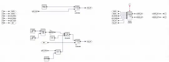
The simulation consists of following main modules
- IM model
Dynamic model of the three phase squirrel cage induction motor with following parameters of the T equivalent circuit:
$$R_s=0.294\,\Omega $$ $$L_{sl}=0.00139\,\mathrm{H} $$ $$R_r=0.156\,\Omega $$ $$L_{rl}=0.0007401\,\mathrm{H} $$ $$L_m=0.041\,\mathrm{H}$$ (model itself is for inverse \$\Gamma\$ equivalent circuit). And following
nameplate parameters: $$V_n=230\,\mathrm{V} $$ $$I_n = 39.5\,\mathrm{A} $$ $$f_n=60\,\mathrm{Hz} $$ $$p_p = 3 $$
- Observer
Very simple "observer" which calucates in open-loop the estimate of the components of the unmeasurable rotor flux and based on that determines orientation of the space vector of the rotor flux for the field oriented control algorithm.
- Control algorithm
Produces components of the reference stator voltage in the stationary reference frame.
- Vector control
All the above mentioned blocks are continuous time domain blocks.
As far as the field oriented control algorithm I have attempted to model the rotor flux oriented control algorithm. The control algorithm in my very simple form consists of two PI controllers. One for the flux component of the stator current (\$i_d\$) and the second one for the torque component of the stator current (\$i_q\$). The reference value of the flux component (\$i^*_d\$) has been set according to the nominal value of the rotor flux (\$\psi_{rn} = 0.55\,\mathrm{V}\cdot\mathrm{s}\$). The reference value of the torque component (\$i^*_q\$) is set to zero for \$0.7\,\mathrm{s}\$ from the beginning of the simulation (excitation phase where the flux in the machine is built). After expiration of this time the (\$i^*_q\$) is set to 10 A (arbitrarily chosen value so that some torque demand is present).
Before simulation start I have set initial condition \$\psi_{r\alpha}(0) = 0.01\,\mathrm{V}\cdot\mathrm{s}\$, \$\psi_{r\beta}(0) = 0\,\mathrm{V}\cdot\mathrm{s}\$. As soon as I have started the simulation I have received following results.
- Motor mechanical speed
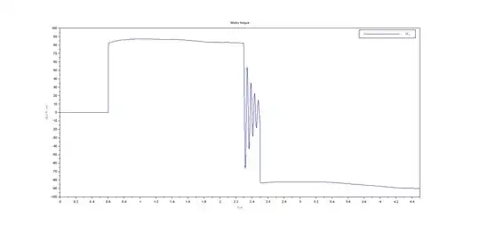
- Motor torque
- Reference and actual value of the flux component of the stator current
- Reference and actual value of the torque component of the stator current
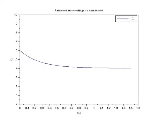
- Reference value of the stator voltage in the d axis
- Reference value of the stator voltage in the q axis
- Module of rotor flux
- Sine and cosine of the argument of the estimated rotor flux space vector in the stationary reference frame
Based on the graphs above it is obvious that mechanical speed of the motor is zero because motor doesn't produce any torque. The torque is zero because the actual value of the torque component of the stator current (\$i_q\$) is zero (despite the fact that reference value of the q component of the stator voltage is non-zero).
My problem is that I don't understand why the \$i_q\$ is zero despite the fact that \$u^{*}_q \neq 0\$. Can anybody help me understand what is wrong in my simulation? Thanks for any idea.
UPDATE:
I have found the cause of the weird outcomes of the simulation. The problem was in the blocks for Forward and Inverse Park transform - namely the misconnection inside them.
I have also reworked the internals of the Control algorithm block based on the AN1930. So I have placed the rotor flux controller and the speed controller in front of the Vector control block.
The other change which I have done is a cleanup inside the Vector control block.
For the sake of completeness I will also add the implementation of the PI controller block
With those changes I have simulated following scenario:
$$t=0.0\,\mathrm{s}: \omega_{ref} = +120\,\mathrm{rad}\cdot\mathrm{s}^{-1}$$ $$t=2.5\,\mathrm{s}: \omega_{ref} = -120\,\mathrm{rad}\cdot\mathrm{s}^{-1}$$
I have received following outcomes:
- Motor mechanical speed
- Motor torque
- Reference and actual value of the flux component of the stator current
- Reference and actual value of the torque component of the stator current
- Reference value of the stator voltage in the d axis
- Reference value of the stator voltage in the q axis
- Module of rotor flux
- Sine and cosine of the argument of the estimated rotor flux space vector in the stationary reference frame
- Stator currents
Most of the simulation results is much better but still there are several graphs which content seems to me weird. Namely I have been looking for answers to below given questions:
- Why the torque component of the stator current oscillates?
- Why the module of the rotor flux isn't constant during the whole simulation?
- Why the d component of the reference stator voltage has this waveform?
- Why the q component of the reference stator voltage has this waveform?
Does anybody know the answer to any of the above mentioned questions?
