2

I'm totally lost with the behavior of this simple schematics. issue http://img72.imageshack.us/img72/9421/issueh.png

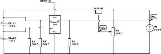
Once the charging process starts, Arduino's voltage reading becomes very different (should I say wrong) from the one voltmeter shows, as if there was some invisible 10 Ohm resistor in place of the switch, resulting in huge voltage drop due to some 0.5 A current. How can Atmega's A1 & A2, both being connected to the same wire, indicate different voltages?

Are here some internal Atmega's clamping diodes kicking-in or else? As for the internal resistance of the batteries, I presume voltmeter correctly indicates 0.2V drop.

ps: yes, I know, the schematics is incomplete. It has no protection resistors on Analogue input pins, also, the high-side MOSFET should replace the switch.

Brian Carlton
  • 13,252
  • 5
  • 43
  • 64
FlegmatoidZoid
  • 511
  • 4
  • 17
  • 2
    If you're planning to update your schematic, please read this: [Ruled & Guidelines for Drawing Good Schematics](http://electronics.stackexchange.com/questions/28251/rules-and-guidelines-for-drawing-good-schematics). – Nick Alexeev Jan 02 '13 at 22:46
  • Hey what about the lady engineers out there? (You should remove unnecessary salutations, greetings, thanks, and the like.) – JYelton Jan 02 '13 at 23:01
  • You need to show the detail on how the Arduino is connected and powered. Your circuit contains no current limiting (relying on the DC source to perform this function -- a bad idea), so if your Arduino is connected to the same DC source, the voltage of the DC source will crash at the start of a deep charge cycle and you may get unpredictable behavior out of your ADC due to problems with the reference. – DrFriedParts Jan 02 '13 at 23:11

2 Answers2

1

According to your schematic, when you close the switch you will short the +5V 3A rail to the 2.6V battery rail - this is not good unless you are controlling the charge current (Have you measured the current?)

Your wiring/switch could account for the drops between inputs if there is a lot of current flowing - for example at 3A, you only need 3A * ~330mΩ to give you a drop of 1V.

More info would help, e.g. on the type/capacity of batteries, type of supply, how you are confirming the A1 A2 voltages, etc.
A constant current charge is preferable. It's also possible your bench supply is just showing you the "set" voltage, but if it's in constant current mode the actual voltage will drop as the circuit draws more current - I would measure voltages with a multimeter at various nodes to make sure of what is happening, and also measure resistance across the switch to the supply (i.e. between the A1 and A2 nodes)

Oli Glaser
  • 54,990
  • 3
  • 76
  • 147
0

I've red though your recommendations and tried another test

Here goes the updated circuit:

test circuit Batteries - NiCd, 1.2V, 2500Ah

PSU is LM2596S based buck converter (16V/5.4A -> 5V/3A)
Current limiting device is a P-channel MOSFET (IRF5305). With its gate pulled down to ~0.65V it passes exactly 0.25A.
Current measurements were confirmed with two separate ammeters plus with a shunt resistor (5W/1Ohm resistor in place of CElL1 & CEll2).
Voltages were measured with ATMEGA 2560 ADC. Also, each measurement was confirmed with the two separate voltmeters.

CELL1 / CELL2 resistance (disconnected) = 165 Ohm

The results under no load (Voltmeter / Atmega):

  • PSU(V): 5.03 / 5.03
  • A0(V): 1.36 / 1.37
  • A1(V): 2.74 / 2.72
  • A2(V): 5.03 / 5.03

The results under load 0.25A load (Voltmeter / Atmega):

  • PSU(V): 5.01 / ---
  • A0(V): 1.64 / 1.68
  • A1(V): 3.25 / 3.28
  • A2(V): 4.85 / 4.9

The results under load 0.5A load (Voltmeter / Atmega):

  • PSU(V): 5.01 / ---
  • A0(V): 1.67 / 1.69
  • A1(V): 3.34 / 3.39
  • A2(V): 4.82 / 4.86

The "under load" voltage drop:

  • 0.25A results in 15mV delta (o.06 Ohm)
  • 0.5A results in 19mV delta (0.38 Ohm)

considering the measurement bias, I've come to a conclusion its a breadboard which introduces 0.05 Ohm resistance. I've tried connecting A2 pin directly to PSU's Vcc via 20cm wire and yes, the voltage drop reduced by 12mV (2mV@0.25A and 7mV@0.5A)!

The one weird thing though - why does increasing the charging current also increases the voltage over the battery cells (NiCd)?

FlegmatoidZoid
  • 511
  • 4
  • 17