4

I'm trying to get an RF transmitter/receiver pair from digikey to work with my Arduino Uno/Mega ADK. But it seems neither the transmitter nor the receiver example are working with any of my Arduinos. At the moment I focused on the transmitter for now (hooked up the UNO) as its more obvious to tell when its working or not. I'm using Arduino IDE 1.0.1 with VirtualWire 1.9 (the one coming with 1.0.1 didn't compile).

Now when I understand the sketch correctly this should send "hello" in an infinite loop and blink the onboard LED everytime. When I reset the Arduino UNO I can see the TX LED blink once for a very short amount of time (which is the serial.print I guess) and after that the onboard LED is just constantly glowing. I have honestly no idea why this isn't working. Everything looks correct to me.

The model name of the transmitter is QAM-TX2-433-ND but I guess this is more of a code than a hardware problem? Though here is the datasheet of the transmitter if thats of any help: http://www.quasaruk.co.uk/acatalog/DSQAM-TX2-2.pdf

This is the code of the transmitter example from the VirtualWire libary

#include <VirtualWire.h>

void setup()
{
    Serial.begin(9600);   // Debugging only
    Serial.println("setup");

    // Initialise the IO and ISR
    //vw_set_ptt_inverted(true); // Required for DR3100
    vw_setup(2000);  // Bits per sec
}

void loop()
{
    const char *msg = "hello";

    digitalWrite(13, HIGH); // Flash a light to show transmitting
    vw_send((uint8_t *)msg, strlen(msg));
    vw_wait_tx(); // Wait until the whole message is gone
    digitalWrite(13, LOW);
    delay(200);
}

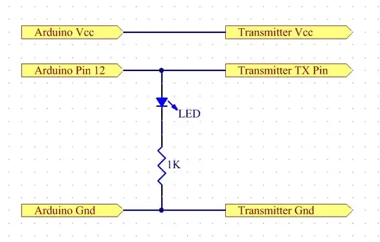
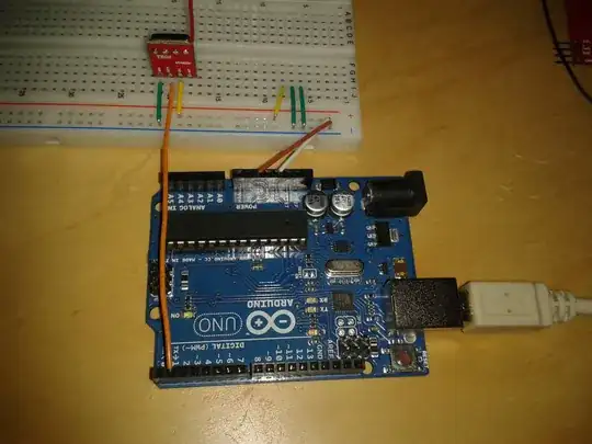
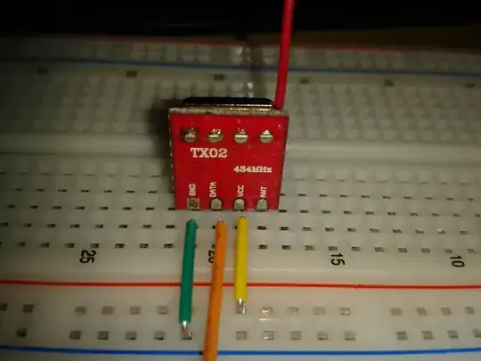
And here two pictures of the hook up to the arduino: enter image description here

close up of the transmitters pin-out

EDIT: Ok so the LED problem was super simple, I just didn't specified PIN13 as output. Though I still don't know if the transmitter is acutally sending something, I have my ADK hooked up to the reciever and its running the reciever example from the VirtualWire libary. It should blink and print the "hello" message via serial but its not doing that. Now its hard to say if this is a reciever or transmitter problem now.

receiver sketch:

#include <VirtualWire.h>

void setup()
{
    Serial.begin(9600); // Debugging only
    Serial.println("setup");
    pinMode(13,OUTPUT);
    // Initialise the IO and ISR
    //vw_set_ptt_inverted(true); // Required for DR3100
    vw_setup(2000);  // Bits per sec

    vw_rx_start();       // Start the receiver PLL running
}

void loop()
{
    //Serial.println("Recieving...");
    uint8_t buf[VW_MAX_MESSAGE_LEN];
    uint8_t buflen = VW_MAX_MESSAGE_LEN;

    if (vw_get_message(buf, &buflen)) // Non-blocking
    {
    int i;

        digitalWrite(13, HIGH); // Flash a light to show received good message
    // Message with a good checksum received, dump it.
    Serial.print("Got: ");
    
    for (i = 0; i < buflen; i++)
    {
        Serial.print(buf[i], HEX);
        Serial.print(" ");
    }
    Serial.println("");
        digitalWrite(13, LOW);
    }
}

Deleting the if (vw_get_message(buf, &buflen)) statement gives me a lot of garbage on the serial monitor, so I can receive at least something.

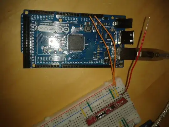
And here two pictures of the circuit again (forgot to insert the data cable for the photo, it was connected to the second pin from left to the receiver and to pin 0 on the arduino):

enter image description here

enter image description here

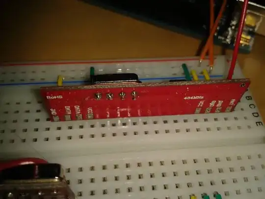
And the datasheet: http://www.quasaruk.co.uk/acatalog/DSQAM-RX4-1.pdf

Davide Andrea
  • 16,164
  • 4
  • 33
  • 62
timonsku
  • 1,368
  • 3
  • 14
  • 30
  • Sounds like a software problem right now to me. The fact the onboard LED is stuck 'on', looks like it might be waiting at ``vw_wait_tx()`` before it will continue operation. – dext0rb Dec 30 '12 at 19:37
  • I tried it with `vw_wait_tx()` commented out but I had the same result. – timonsku Dec 30 '12 at 20:00
  • I had a problem using this RX module. I almost got crazy when I decided to contact Quasar. PIN 6 should be left N/c !!!!!!!! Datasheet is wrong !! Regards –  Jun 20 '14 at 07:43
  • Yes, Gonzalo S, it is likely to be an AF output before the data splicer, if this module is following the trends set in other modules. However the question didn't cover this. – James Cameron Jun 20 '14 at 09:16

1 Answers1

5

The problem seems to be rather banal.

You forgot to properly set:

pinMode(13,OUTPUT);

in the setup() function.


Incidentally, your code should actually be working, with the exception that the LED state is likely constant. It should be transmitting anyways.


Further Edit:

Ok, I've dug into the virtualwire library a bit more, and I think I see the problem

Mainly, the default configuration for the VirtualWire library TX pin is pin 12.

Basically, you have connected the transmitter to the wrong pin (in the pictures, you have it connected to pin 1).


Adding a TX activity LED to the module:

Note that this will only work properly with vw_set_ptt_inverted(true); commented out.

Connor Wolf
  • 31,938
  • 6
  • 77
  • 137
  • Oh thats true but shouldn't I see TX blink aswell whenever "hello" gets send? LED is blinking now but TX is still always off. Thats whats actually concering me that nothing gets send through the TX pin apparently. – timonsku Dec 30 '12 at 20:04
  • 1
    @PaulGreen - Do you mean the built-in "TX" LED on the arduino? That will only blink when the serial connection to the computer has activity on it. The virtualwire library will not cause it to become active. – Connor Wolf Dec 30 '12 at 20:07
  • Remember, in your setup, you have **two** TX lines. The one between the Arduino and your computer, which is the one with the TX led on it. The wireless transmitter has a *separate* TX line, and there is no LED on that. – Connor Wolf Dec 30 '12 at 20:09
  • oh I see, I didn't know that! I will try and see if the MEGA is recieving anything now. – timonsku Dec 30 '12 at 20:10
  • It should be possible to wire up another LED on your breadboard to give you a activity indication for the wireless transmitter TX line too. – Connor Wolf Dec 30 '12 at 20:13
  • Ideally, you would simply probe the TX line going to the transmitter with an oscilloscope. That would tell you exactly what is going on with the connection. However, you may not have an oscilloscope (you should look into getting one, if you can. It's the most useful tool after a multimeter!) – Connor Wolf Dec 30 '12 at 20:14
  • No sadly I don't have an oscilloscope. How would I connect the LED, just put it between arduino and data input and the connect the other leg to ground? I edited the post with info about the reciever, so far the reciever is still getting nothing. – timonsku Dec 30 '12 at 20:25
  • @PaulGreen - See further edits. – Connor Wolf Dec 30 '12 at 20:48
  • Ugh! Thanks so much for looking into this, this was indeed the problem. Hooking up the transmitter to 12 and the reciever to 11 gave me an output on the serial monitor. Output is 68:65:6C:6C:6F which is "hello?" in ascii, I guess the ? is some sort of "end character" for the message? Again, thanks a lot for your help! – timonsku Dec 30 '12 at 20:55
  • nvm I just had a space in the hex editor, there is no ? – timonsku Dec 30 '12 at 21:05
  • @PaulGreen - No problem. It's what this site is for. – Connor Wolf Dec 30 '12 at 21:09