2

Some time ago I bought a little amplifier kit on Banggood based on the LM386 chip. After soldering the kit I tested it, and it worked great, so I decided to buy a few more of these kits to incorporate them in some audio projects I was working on.

Now I'm working on an 8-step sequencer and I wanted to add this amplifier to my project, and so I decided to draw the schematic for the amplifier and add it to the schematic of the sequencer.

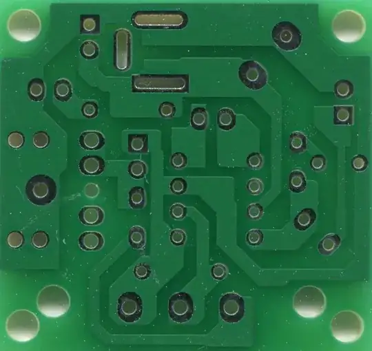
I've scanned both sides of the PCB, drawn out the traces in Paint.Net and merged both sides to get a better view of the connections between the components. Finally, I drew the schematic in EasyEDA, based on the PCB and my drawings. Here are the steps I took: Front side of the PCB Back side of the PCB - flipped Traced backside layered on top of the front side of the PCB Final schematic
During this process I was (and still am) very confused about the purpose of jumper JP1. If I haven't made any mistakes, bridging jumper JP1 would mean short-circuiting the audio input, and I have absolutely no idea what that would be useful for. Is this an error in the original design? Have I missed something in the PCB?

Basically my question is: what is the purpose of this jumper, if it is not an error?

Also, as I'm still learning how to draw schematics, I've taken pointers from rules and guidelines for drawing good schematics but if anyone has any comments on how to improve my schematic, I'd obviously like to hear these as well.

Marlon
  • 33
  • 3
  • 1
    Where's the jumper on the board? – Andy aka Oct 03 '20 at 15:19
  • 4
    It looks to me like that's labeled J5, not JP1. It's probably an alternate input for feeding the signal in via common jumper wires, rather than using the jack. – Mark Leavitt Oct 03 '20 at 15:20
  • It may allow direct wired connections (via matching 2-pin connector) instead of using the jack. Just like H1 does for power. –  Oct 03 '20 at 15:23
  • @MarkLeavitt you are correct, it is J5... Initially I had placed a 2-pin header labeled J5 because I didn't know the symbol for a jumper in EasyEDA (or else), and apparently I forgot to alter the label. An alternate input? I hadn't thought of that! – Marlon Oct 03 '20 at 15:23
  • Minor correction: The sleeve connection on your "A1 Audio In" jack should be connected to ground. Also, the audio signal should be connected to the "tip" contact at the very bottom. There should be no connection to the middle switching contact. – Dave Tweed Oct 03 '20 at 16:25
  • @DaveTweed thank you, I missed that one indeed. I still have one question though: as it's prefered in schematics to have VCC at the top and GND at the bottom, would it be preferred to flip the symbol upside down so as to have the sleeve connection on the bottom? Or would you keep the symbol as is (but as a result have to cross the GND over the other connections)? – Marlon Oct 03 '20 at 19:26
  • Sure, I would flip it over. – Dave Tweed Oct 03 '20 at 19:36
  • The capacitances of C5 and C6 are so small that there will be no bass low frequencies. Instead of having R2, the volume control should be a logarithmic audio one. – Audioguru Apr 25 '22 at 22:00

2 Answers2

3

It's not a jumper. It's a 2-pin 0.1" PCB strip header, into which you can plug in a 2-socket "DuPont" plug (or two "DuPont" wires) with an audio signal.

Whoever designed the PCB didn't have / didn't find the Schematic symbolfor a plain 2-pin 0.1" PCB strip header so they used the one for a 2-pin 0.1" PCB shunt, since it has the same pads spaced the same way.

Davide Andrea
  • 16,164
  • 4
  • 33
  • 62
2

Putting a shorting jumper on J5 will connect the input tip pin to ground, which will stop any signal getting through, so it's clearly not a jumper. So, what is it for? It's actually just a duplicate input connector, should you want to connect the signal in via standard push-on connectors e.g.from an Arduino, rather than using a normal 3.5mm jack lead. Note also that the 3.5mm jack socket is a mono amp feed which ignores the middle ring contact in a stereo lead. So, if you are using a stereo source (e.g. an MP3 player), you will need to use a stereo to mono convertor or you will only get one channel (L or R) playing.

Mike E
  • 21
  • 2