0

Problem description:

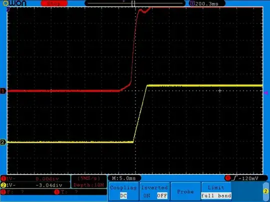
Power supply, for some reason, false-starts on power on of the device:

enter image description here

the red is system +5 V supply rail, and yellow is my device's 3.3 V buck converter powered from the system's 5 V. You can see the power surge when switch is being turned on, and 3.3 V power supply also false-starts.

Here's more detailed picture of what is going on:

enter image description here

But in general I can not control what is going on with the system's power supply.

Due to this false start, audio subsystem experiences pop-click sound which I want to eliminate.


Research:

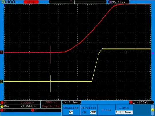
Thus I am looking for ways to suppress this false start influence onto the audio outputs. There's system's RESET signal, which is kind of not logical 1 when false start happens:

enter image description here

Red is reset signal (5V TTL), yellow is 3.3 V converter. Thus it seems I can use RESET signal to control circuit suppressing the audio output.

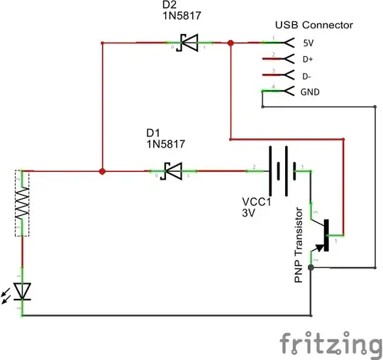
I am simulating the following circuit (which is not my design):

enter image description here

The result of simulation is:

enter image description here

where blue is reset (V3), green +5 V power (V1), and red is an output. Audio input (V2) is always running at 1000 Hz.

The problem is that if power is not yet there, Q2 is off and input audio signal is not pulled down.

I also considered solution based on MAX9892, but its switches are open when power is < 1.7 V, so it must exhibit the same behavior.


Question:

is there any solid-state circuit which would be "normally closed" when power is not in there?

Update, following @bobflux comments:

  1. I connected probes to the input and output capacitors of the 3v3 buck converter:

enter image description here

  1. now connected yellow probe to its alligator clip:

enter image description here

  1. same, closeup

enter image description here

  1. Now things become more interesting. I put my device into another platform, based on ATX power supply, and connect to the same wires. Below is an image when I turn ATX power switch on, but active power is not yet applied to the device (only standby somwhere inside it):

enter image description here

  1. now closeup

enter image description here

  1. and now I press ATX switch to turn main power up:

enter image description here

So the outcome of measurements is that noise comes from main receptacle power wires being connected to the mains, not from device being powered on. The first, non-ATX platform is having virtual ground and only 2 mains power wires, the second, ATX one, is expected to be properly grounded with the scope.

Small addition, it may matter: I use scope and its probes in X1 mode.

Update: agreed it is caused by the common mode transients.

Meanwhile seems I have found the cause of the pops and clicks. It is DAC UDA1334, if powering it down, and then quickly powering it up, the analog and digital parts of it improperly reset and DAC gets arbitrary value. Then, when DAC starts to be driven by writing 0 to it, the output clicks.

I suspect I must do something with Vref input of the DAC ensuring it got as low as 0.75 V during reset so that analog part properly resets. Not sure if it will reset digital part properly though, but hopefully problem is not in digital part, but in analog subsystem power up calibration, then resetting analog part properly will solve the problem.

Anonymous
  • 6,908
  • 1
  • 14
  • 41
  • So, I'd start with: have an enable pin on your 3.3 V buck converter, which you simply slow down enough (~100 µs?) by adding an RC low pass; it's also surprising that you have such a sharp pulse on a 5V supply line that should probably be well-stabilized with a couple caps. – Marcus Müller Oct 02 '20 at 09:11
  • You confuse 5V supply with reset signal. First pic is about powers, and 5V goes up within ~15 ms. Delaying 3.3v may not be a good idea as there're level shifters connected to both powers and not having one part powered properly for some time may negatively affect them. – Anonymous Oct 02 '20 at 09:13
  • yeah, but your 3.3V supply *still* shouldn't try to come up there! That's simply a sign of something not being sufficiently designed with power sequencing in mind, and solving that, maybe not even by replacing the power supply, but simply a massive capacitor on the 5V rail, would get rid of that source of problems... – Marcus Müller Oct 02 '20 at 09:16
  • The 3.3V supply conversion is built on MAX1951, according to its application information. Anticipating your question on increasing the value of C5 in fig. 2a in its datasheet - it is bad idea because if part is not powered, it passes input voltage to the output, frying 3.3V components with 5V. It operates at 1 MHz, thus it is logical that it tries to start within 3-5 us of its input power. – Anonymous Oct 02 '20 at 09:23
  • wait, then there's a bigger picture of necessary power sequencing that we're not getting here, right? – Marcus Müller Oct 02 '20 at 09:24
  • no, I didn't mean C5 in fig. 2a, by the way. I said "enable pin"; so I'd honestly just get a buck controller with a dedicated enable, or you'd have to implement an inverted version of the "OPTIONAL SHUTDOWN CONTROL" block (e.g. with a PNP fed from an RC filter on your 5V) – Marcus Müller Oct 02 '20 at 09:31
  • (your 5V spike suggests C1 in fig 2a is underdimensioned, though! That cap should really absorb a pulse of that duration *easily*) – Marcus Müller Oct 02 '20 at 09:33
  • 1
    The 5V power was measured on the power supply output, seems I must measure the waveform on 10 uF C1 cap directly to get reliable data. I will also see if I can desolder cap I currently use and measure it ensuring it is really 10 uF (it is GRM21BR60J106KE19L) – Anonymous Oct 02 '20 at 09:37
  • Probably a good idea! – Marcus Müller Oct 02 '20 at 09:38
  • I've seen a case like this where the spike was actually a common mode spike due to switching power supply input caps charging when power was switch on. The way to know if this is the case is to probe GND instead of your supplies. I mean, keep the exact same measurement setup, but just move your scope probe tip from VCC to GND. If you still measure a spike that should not be there, this is a common mode issue, and the solution will be different than if it was a spike on your supply. – bobflux Oct 02 '20 at 09:40
  • 1
    I mean on the second scope shot at 5µs/div there seems to be a damped oscillation with dv/dt = 2V/µs ... If there is a 1µF ceramic cap on your supply, knowing that i=Cdv/dt, that implies 2 AMPS of ringing current on your supply, which is suspiciously high. – bobflux Oct 02 '20 at 09:44
  • @bobflux apologies did not get how to measure common mode spike (your first comment). Where must I connect scope probes (each fo them)? The DUT is not having PE wire to it (it is old game console with 2 power wires). The DUT itself is built on a number of TTL components. My device is an addon to the DUT which functions on 3.3v (1.2v and 2.5v). I was checking waveforms for +12 and -12V outputs of the power supply, and there're no such spikes. I also tried another DUT which is being powered by the ATX power supply (properly grounded) and it also has specific clicking sond on power on/off. – Anonymous Oct 02 '20 at 09:53
  • 1
    Use same measurement setup as above where you saw the turn-on spike, repeat the measurement to check the spike is still there. At this point your probe should be on the supply you're measuring, and your scope ground clip on GND. Then just move the scope probe tip to GND without changing anything else and turn the device on again. Since you're probing GND, the scope should display a flat line. If it doesn't display a flat line and you still get a spike, then you were not measuring what you thought you were measuring, which would waste your time solving the wrong problem. – bobflux Oct 02 '20 at 10:01
  • ...sorry, forgot this: in order to trigger the scope, set trigger level so it triggers on the spike (not the power supply ramp-up which won't be there since you're probing GND). Or just use two channels as you did before, on on VCC for triggering, and other channel probe on GND. If the probe on GND doesn't give a 0V flat line, something's wrong in the measurement setup. – bobflux Oct 02 '20 at 10:04
  • Probing problem, not a real problem. – Andy aka Oct 02 '20 at 11:26
  • OK so it's either a common mode transient from the mains power switch, or magnetic field being picked up by the loop antenna formed by the probe ground alligator wire. Using the tiny ground clip instead will remove the antenna, which will tell you which problem it was. Probably common mode. If the audio equipment connected to the DUT plays a loud "crack" when the mains switch is actuated, this is due to it detecting this common mode transient as audio signal. Try a ferrite clamp on the mains lead... – bobflux Oct 02 '20 at 16:33

2 Answers2

3

Red is system +5 V supply rail, and yellow is my device's 3.3 V buck converter powered from the system's 5 V. You can see the power surge when switch is being turned on, and 3.3 V power supply also false-starts.

Sanity check:

enter image description here

+5V and +3V3 show very similar damped ~500kHz oscillation on scope display. In fact, almost exactly the same signal considering one is 1V/div and the other 2V/div. It's very much like both probes are measuring the same thing.

However, +3V3 is the output of a Buck converter. Presumably there are enough decoupling capacitors on +3V3 rail, since when the buck is on and delivers +3V3, there is no visible ripple on the scope:

enter image description here

So, the buck's L and C do remove the switching noise, yet the ~500 kHz damped oscillation at turn-on which is present on +5V would somehow pass through the same buck LC filter and end up in the output unattenuated?... This is not realistic.

Besides, you got 2V/µs slew rate on the damped oscillation ; on a properly decoupled rail this means huge transient current which would have to come from somewhere.

So. You're measuring pretty much the same signal on both channels probing unrelated power rails. So they must be connected pretty solidly at "highish" frequency. The only HF connection between these rails is not through the inductor, but through ground and decoupling caps.

So, I think you're not measuring what you think you're measuring. There's probably something there, but it is not a 2V/µs, 500kHz damped oscillation on both power rails at the same time.

It could be a interference from the switch arcing or something else, being picked up by the scope's ground alligator clip lead acting as a loop antenna. So you can use the tiny ground spring instead.

Or it could be common mode noise that the probe and scope interpret and display as actual signal.

The way to check your measurement is to repeat it, for example repeat the measurement in your first screenshot, make sure you get the spike. Since the scope triggers on Channel 1, now move Ch2 probe from where it was to somewhere nearby on the ground plane, and repeat the measurement. Ch1 should show the exact same signal as before, and the scope should trigger. Ch2 should show a 0V flat line since you're probing GND. If it does not, and it shows a spike that shouldn't be there, then your problem is either a common mode voltage spike at turn-on, or something which generates a large current pulse in the ground.

Or perhaps you've connected your ground alligator clip in the wrong place...

If you are still using the ground alligator clips, you can also unclip Ch2 ground alligator from the circuit and clip it on the tip of Ch2 probe tip, then repeat the measurement. This will measure what the loop antenna is picking on. If the scope displays a spike on Ch2 with such a setup, then you should really use the tiny ground springs and not the alligator clips.

If this is true, then the problem is not what you thought and the solution you're working on (a muting circuit) won't solve it.

bobflux
  • 70,433
  • 3
  • 83
  • 203
  • 2
    ohhhhhh good sanity check! "If the output of your inductive converter, a well capacitively stabilized thing swings exactly like your main supply, you're not measuring what you think you're measuring"! – Marcus Müller Oct 02 '20 at 10:45
  • 1
    updated the question with more measurements – Anonymous Oct 02 '20 at 11:47
2

is there any solid-state circuit which would be "normally closed" when power is not in there?

Depletion mode FETs.

All JFETs are depletion mode...

Maybe not so convenient to use; you need something like -10V on the gate (Vgs) to open the switch, 0V to close (or pull it to +V via several megohms). But if you have +/-12V, go for it. If you have +/-5V, it may be possible with careful device selection, or the relatively rare (as in I can't think of any) depletion mode MOSFETs.

  • Or a latching mini-relay to shunt the audio to ground. 100ms after power-good, open it. Close it on power-down. – rdtsc Oct 02 '20 at 12:24
  • Latching relay may be caught in the wrong state. A non-latching (NC or changeover) relay would work if the power consumption is tolerable. –  Oct 02 '20 at 12:35