8

I have an ATMEGA328p-pu arduino with an LED + shift-register strip circuit attached over SPI. When it turns on, it increases a variable in EEPROM to advance the display mode.

  • We have the brownout detector set to level 1 (2.7V).
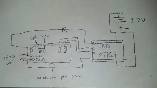
  • There is a 1500 uf capacitor attached in parallel to the power leads to, hopefully, keep the arduino from changing modes on a physical impact, since the battery terminals can disconnect slightly for a millisecond (?) or so.
  • There is a diode on the cap's positive lead to prevent the cap from discharging into the LEDs, so it only buffers the arduino.
  • There is also a 1000 ohm resistor in parallel across the cap to drain it since it was holding a voltage, which we assume was behind a problem where the chip wasn't lighting up the LED circuit sometimes on boot.
  • The arduino pro mini and strip are rated at 5v, but we routinely run them at 3.7V so they can be powered with a single Li-Ion cell.

Sometimes after sitting for 10 or 15 seconds, the circuit won't light up. Sometimes after disconnecting the battery and reconnecting it several times in a row, it will then light up.

Could anybody recommend a better way to provide a power buffer to the ATMEGA (but not to the LED strip)? Are we doing it correctly for the most part?

Diagram (sorry if it's messy, I can have my friend redo it in Illustrator if it's unclear, just might take a few hours): Circuit Diagram

blkmage
  • 81
  • 3
  • 2
    Can you draw an circuit diagram of the situation with the AVR, power supply, resistor, capacitor, diode, ... – jippie Dec 28 '12 at 18:03
  • Is the only reason you need this "buffer" because the battery terminals can disconnect slightly if bumped? If so you should just remove the connector and solder the wires directly to the board. – Garrett Fogerlie Dec 28 '12 at 18:08
  • To echo jippie, you've started with a good written description, the addition of a schematic will help immensely. If you have problems posting there is help available. – placeholder Dec 28 '12 at 18:32
  • Thanks for the feedback everybody, I'm working on a diagram now. @GarrettFogerlie The use of a removable battery the terminals is a design requirement right now, but I appreciate the suggestion. – blkmage Dec 28 '12 at 18:42
  • 2
    Your bleeder resistor is on the small side, consuming substantial power compared to typical standby needs. If you can detect brownout in software, set up a program which "counts" on the UART output starting from brownout and monitor that while pulling the power supply and see how long it runs, calculating back through he baudrate. Also beware the possibility of inadvertently powering peripherals through data lines. – Chris Stratton Dec 28 '12 at 19:14
  • Thanks @ChrisStratton, great suggestions. One thing we just did to troubleshoot it was remove the entire cap and diode piece, leaving only the 1kOhm bleeder. The problem remained, so I guess we have narrowed it down a bit. There is something about having that resistor in parallel with the power rails that causes erratic behavior between the arduino and the LED strip. – blkmage Dec 28 '12 at 19:47
  • That should not be the case, unless the LED strip is requiring very close to the positive rail to reliably read a 'high', in which case the low value bleeder resistor may be helping pull enough current through the diode to activate its full voltage drop and make the atmega's 'high' output not a high enough voltage for the LED circuitry. You could try giving the LED strip it's own independent diode so both circuits see similar supply voltages. Also please clarify if this is an in-operation problem, or more of a problem with power-on-reset not reliably happening. – Chris Stratton Dec 28 '12 at 19:59
  • @ChrisStratton Thanks again, at this point it is a problem with power-on-reset. Sometimes the strip will turn on normally, other times there will be a 5-10 second delay before the strip turns on. Most rarely, it won't turn on at all (or would turn on after so long that we gave up). We just troubleshot a problematic arduino on a different strip and the results are the same. A small percentage of arduinos we have behave this way, most don't. Working on a bigger sample size right now to figure it out. – blkmage Dec 28 '12 at 20:19
  • 1
    Maybe you can try to give the arduino some independent output (serial, it's own discrete LEDs) so you can do a little debug indication there that the arduino has reset, distinct from it's success in talking to the LED strip. I'm assuming the LED strip doesn't even really have a reset, distinct from the ordinary progression of it's states every time you access it? – Chris Stratton Dec 28 '12 at 21:22
  • @ChrisStratton issue was totally unrelated to the cap, diode, and bleeder, see my comment above. Very grateful for your help :) – blkmage Dec 28 '12 at 22:03
  • All the stuff I posted was misleading, we fixed it by turning off fuse bit BOOTRST Go figure :p Thanks for all the help, especially @ChrisStratton – blkmage Dec 28 '12 at 21:54
  • No, that is incorrect. The fuse controls where program execution starts. Perhaps going through a bootloader is slowing you down, and not doing so helps. **But you have not understood or solved the actual problem**. – Chris Stratton Oct 12 '15 at 16:10

1 Answers1

3

You can use a super capacitor (1F/5.5v) after the diode, connecting it directly to the VCC and GND. This will help you in buffering the power.

Chetan Bhargava
  • 4,612
  • 5
  • 27
  • 40