I've been playing with home automation for a while now (mostly Sonoff) and recently discovered Shelly.cloud. I'm fascinated by the fact that most of their relays use a mains connected switches to interact with external inputs (see image below) - fascinatingly brilliant as this allows one to leverage existing wiring to retro-fit automation products into existing installations.
But how does it work (the switch part)?
These devices are based on the ESP8266EX (PDF) wi-fi microcontroller that uses 3.3V. This part I get - from what I can see on photos they use a AC-DC on-chip converter, the Shelly 1 (see FCC entry) uses a LNK304DN (PDF) to convert mains to 12V and then they bring that down to 3.3V somehow (I assume something similar to a PMP4536 (www)).
Having worked on ESP8266 I know that it has IO pins that one can use to measure either digital variance or pull-up or pull-down ... but that's all in VCC (3.3V). How on earth is the external button press being detected? And this thing works in both power modes, i.e. 220VAC and 12VDC modes.
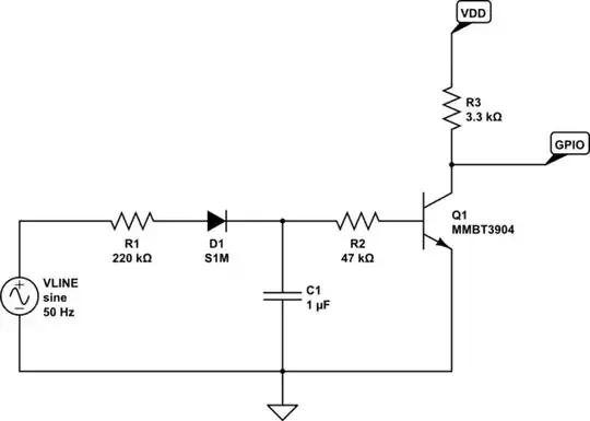
This question pertains specifically to the theory of how one would go about detecting a 220VAC ON state and translate that to signal that can be used in a 3.3VDC microcontroller (think in terms of the example of using an Arduino to detect if a light is on or off).

Another of their products (Shelly Dimmer) has two SW pins and from some close up photos each has a 240 kΩ resistor and then a S1M diode ... but I can't see more from just the photo.
