1

schematic

simulate this circuit – Schematic created using CircuitLab

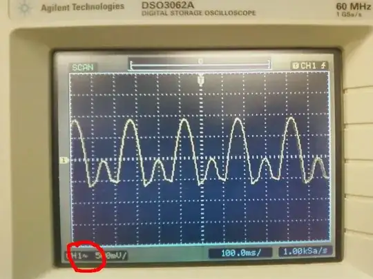
I have a constant current load circuit using a sense resistor and discrete quad op-amp set up as a 3 op-amp instrumentation amplifier and using the 4th to drive the gate of a MOSFET. The circuit oscillated for a long time until I dropped the gate driving op-amp feedback resistors to fairly low values and then it worked fine for a while. I did some load testing of the MOSFET itself (controlling the gate with a POT) to see how well it could handle heat and if the heatsink would do any good. It got crazy hot (starting melting it's own solder) but it still works and isn't shorted. I could try replacing the MOSFET with a new and less abused one but I'd like to have this circuit be less vulnerable to oscillating in general so if I can get it working with this one I'd prefer.

Actual circuit build

Oscilloscope trace of the MOSFET gate voltage

Jonathan
  • 98
  • 6
  • 2
    The circuit would be *much* clearer if you drew it using individual opamp symbols. – Peter Smith Sep 26 '20 at 13:49
  • 1
    Please post a schematic of the circuit, with logical flow of signals from left to right, +ve to top, ground to bottom. Use the built-in tool, edit your question, hit the 'resistor, capacitor, pencil' button to get the schematic editor. I'd love to help answer your question (I reckon you have too many opamps in series, leading to too much phase shift) but I'm not going to put the effort in to redraw your wiring diagram into a schematic. That's your job if you want people to spend time on your question. – Neil_UK Sep 26 '20 at 13:49
  • 1
    Indeed the "schematic" isn't clear **at all**. Sorry but it's a mess, you've drawn things showing how everything connects but not with a focus on how the circuit **works**. I already see strange things: the **source** of the N-channel MOSFET is directly connected to battery negative while the sense resistor is in series with the **drain**. For a **current source** I expect the sense resistor to be connected to ground and the source of the MOSFET. The transistor might be in a **common source** configuration this way and that introduces **voltage gain**, which makes oscillations happen. – Bimpelrekkie Sep 26 '20 at 13:53
  • A proper logical schematic please. Nobody wants to try and figure out how each op-amp is wired from a package view. – Andy aka Sep 26 '20 at 13:55
  • Search for "how to draw schematics" on this site. As noted, we will try to help but we won't if we have to try and redraw your circuit. – Peter Smith Sep 26 '20 at 14:01
  • I've linked to one of the many answers this site contains about using MOSFETs and op-amps to produce constant current generators. Almost certainly it will be a duplicate of the one I linked or one of the many others that ask the same question about unwanted oscillations. See [this site search engine for others](https://electronics.stackexchange.com/search?q=op-amp+and+MOSFET+oscillating+user%3Ame). There are much better circuits than trying to use an InAmp and floating current sense BTW. – Andy aka Sep 26 '20 at 14:05
  • 1
    Dang folks, didn't even have time to finish redrawing the schematic as requested :( new people have to start somewhere and I'm feeling a bit piled on. I am trying to do high-side sensing to avoid shifting ground, @Andy aka I'll try the BJT follower in the linked question, didn't have any to play with when I started this but I do now. Also what are some of the "much better circuits"? I want to keep the high input impedance as I'm doing battery capacity testing and don't want to load the battery in parallel to the sense resistor. – Jonathan Sep 26 '20 at 14:33
  • Indeed you're not using the "standard" way of making a current source, by "standard way" I mean the type of circuit that is discussed here: https://circuitdigest.com/electronic-circuits/voltage-controlled-current-source-circuit-using-op-amp I'm **not** saying that your setup cannot work, it probably can, **but** as I said, you're using the NMOS as a **common source** and that is **asking for trouble** as it introduces extra gain and **pole** (at a nasty frequency) in the loop transfer. Also needing **4 opamps** makes this thing **overcomplicated**. – Bimpelrekkie Sep 26 '20 at 15:24
  • @Jonathan yeah sorry. Things can move quickly round here. Shifting ground to the load is totally what the MOSFET does in order to produce constant current through the load. The BJT follower can be changed to a source follower but also be aware of the extra problem with the MOSFET and that making the op-amp into an integrator will solve those xtra problems. – Andy aka Sep 26 '20 at 16:15

0 Answers0