1

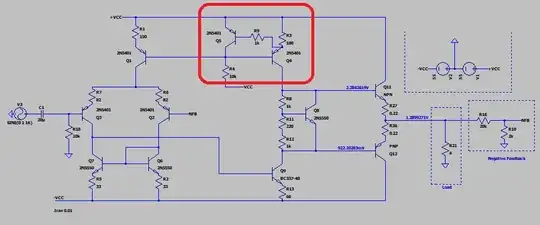
I'm playing around with the circuit below (it's a very slimmed down version of Figure 11.10 from High Power Audio Amplifier Construction Manual pg 348)

Can anyone explain what it is in the circuit that is causing the positive swing clipping at ~ 3V when I use a load of 4ohms.

When I use 50ohms the clipping goes away.

enter image description here

Many Thanks

Cdevelop
  • 187
  • 8
  • You have +Vcc, -Vcc, but also with R4 something called Vcc. What is that value? It's not the same as the other two. – jonk Sep 25 '20 at 07:25
  • @jonk if you look really carefully at it, it's likely it's -Vcc and the minus sign is merged into the blue net line. – Andy aka Sep 25 '20 at 08:03
  • @Andyaka I did look carefully at it. Zoomed WAY up on it, in fact. And since you've identified the same section as a likely culprit now I think we may be in agreement except that I still think the OP just labeled the wire and didn't actually connect it up. – jonk Sep 25 '20 at 16:09
  • @jonk - the blue node line definitely turns black at the end!! If he didn't make a connection to that wire nuthing would work properly. – Andy aka Sep 25 '20 at 16:11
  • 1
    @Andyaka Yeah, when I pixel in I can see a spot or two there. But it's not connected. It overlaps the wire. The OP missed. Take LTspice, draw a wire and then add -Vcc label. Zoom up and look. It will NOT look the same, if you connected it up properly. – jonk Sep 25 '20 at 16:15
  • I never use LTSpice since it gave me such hassle about 3 years ago. I was forced to use it for one particular job and it vomited an anomaly that caused me two weeks of rework. I stick to micro-cap (and have done in the main since I was a wee lad)! – Andy aka Sep 25 '20 at 16:24
  • @Andyaka I'll have to give it a look. I've invested time in LTspice (micro-cap wasn't free back in the day.) But it may be nice to check it out. I teach young people at no charge (classes started last week) who don't have a lot of money nor are they even sure that electronics is something they can stick with. Many won't survive another week. :) Perhaps I should get up to speed on micro-cap, now that it is cheap enough. ;) – jonk Sep 26 '20 at 19:06
  • Full blown version with all the libraries are free. It’s the best but, maybe it’s the best because I think it is. I would definitely recommend it to new starters. – Andy aka Sep 26 '20 at 20:49
  • @Andyaka I am most definitely going to invest some time into it and see how it goes. I really like having alternatives to offer and something to say about why one may be better for certain things than another. It allows students to pick their poison, so to speak. And the more poison, the better. ;) – jonk Sep 26 '20 at 21:01
  • Anything you find that is confusing you just email me and I’ll do my best. Message aimed exclusively @jonk – Andy aka Sep 26 '20 at 21:53
  • 1
    @Andyaka If something comes up that I can't otherwise work out, I'll give that a try. Thanks! – jonk Sep 26 '20 at 21:59

2 Answers2

3

There's a very good chance that the current limit circuit in the red box is restricting the high level output voltage under load: -

enter image description here

Q5 will be shutting off Q4 as soon as circa 7 mA is flowing through R3. This means that with a max of 7 mA able to drive Q11 (and assuming that Q11 has a hFE of about 100), the current Q11 can supply to the load is about 700 mA max. And, 700 mA into the load of 4 ohms is 2.8 volts i.e. it produces voltage limiting under load.

With a 50 ohm load, 700 mA is able to sustain +35 volts across the load.

Andy aka
  • 434,556
  • 28
  • 351
  • 777
  • Usually, the output stages consist of a Darlington or Sziklai pair so they don't need much base current. Here the driver stage, the input stage, and the current source need to run at very high levels to provide enough drive to the output stage. – Kevin White Sep 25 '20 at 14:10
  • Thanks for the insight, I can see that in my reference diagrams now - had missed that aspect in my attempt to simplify it! – Cdevelop Sep 26 '20 at 13:30
0

Your simulation has adequate +VDD and -VDD to provide 4 ohm load high power.

To extend the output CURRENT, start with using Darlington NPN and PNP for your 2 output transistors.

Then cut R3 and R13 by 50%.

analogsystemsrf
  • 33,703
  • 2
  • 18
  • 46