1

I've found a schematic online for an 8 step sequencer and built it on a breadboard. Before I start experimenting with it and adding features, I'd like to find out if both 10k resistors are needed for each NPN transistor pair.

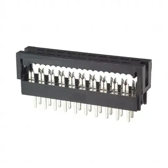
Here is the schematic: 8 step sequencer schematic

As you can see, each output pin of the 4017 decade counter is split to two 10k resistors, each driving one NPN transistor (one for the tone output, one for an LED indicator).

My thought is that I could use a single 10k resistor connected to the output pin, after which the connection would split to the tone and the indicator.

Am I correct? If not, then I would really like to know the reason for the additional resistors.

Thanks!

Marlon
  • 33
  • 3

2 Answers2

1

You could eliminate about half the resistors like this:

schematic

simulate this circuit – Schematic created using CircuitLab

Spehro Pefhany
  • 376,485
  • 21
  • 320
  • 842
  • I understand why not every LED needs its own current limiting resistors, but would you mind explaining why there is no resistor needed to drive the transistors? – Marlon Sep 20 '20 at 16:26
  • The transistors are driven as emitter-followers so no base resistors are required - the base current is limited to the emitter current divided by the gain (\$\beta\$ + 1). \$\beta\$ is typically 100-300. The only downside is that the transistor drops about 0.7V rather than < 0.1V, which can be compensated for by reducing the resistor value a bit. Transistors that are off see some negative base voltage but not enough to be an issue with a 5V supply and jellybean transistors. – Spehro Pefhany Sep 20 '20 at 16:33
0

My thought is that I could use a single 10k resistor connected to the output pin, after which the connection would split to the tone and the indicator.

No. That would not work.

schematic

simulate this circuit – Schematic created using CircuitLab

Figure 1. One of the 4017 outputs drawn in a more conventional manner.

Note in Figure 1:

  • B will be held at the forward voltage of the diode - about 2 V.
  • A will be one diode drop higher due to the VF of Q1's BE junction. It will be held at about 2.7 V.
  • D needs to respond to the discharge / threshold voltage of the 555 and so will ramp up and down with it.
  • C will move up and down with D with an offset of +0.7 V.

If you omit R3 and connect A to C then Q2's base will be held at 2.7 V, the emitter at 2 V and the oscillator will stop. Providing individual resistors for each base makes them independent.

Transistor
  • 168,990
  • 12
  • 186
  • 385
  • Wow, thank you so much for your elaborate (and quick!) answer! That schematic clarified a lot for me! – Marlon Sep 19 '20 at 20:26
  • 1
    Have a read of [rules-and-guidelines-for-drawing-good-schematics](https://electronics.stackexchange.com/questions/28251/rules-and-guidelines-for-drawing-good-schematics). I spent a lot of time in my youth reverse engineering electronics circuits and being able to draw them in a logical format is key to understanding the "schema" of a circuit. – Transistor Sep 19 '20 at 20:34