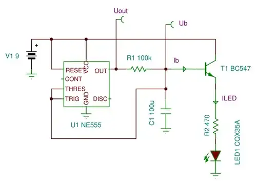
 I searched about this and each explanation did not make any sense,my explanation is that when the OUT pin is HIGH the transistor turns on and the capacitor charges,also the led turns on gradually because the capacitor voltage rises,but when the OUT pin is off ,the capacitor discharges(trough the transistor) and the transistor stays on until the capacitor is fully discharged and when the OUT pin is HIGH it repeats all over again.Am I wrong?
- 53
- 4
-
it's kind of hard to answer without seeing which 555 led fade circuit you have. edit your answer and use the "picture" button to add a picture of the schematic or use the circuit button an draw it. – Jasen Слава Україні Sep 09 '20 at 11:33
-
Here it is @jasen – ROBOTICS Sep 09 '20 at 11:36
3 Answers
You're fairly close with that analysis.
Q1, the transistor is used as an emitter follower, in this configuration it only accepts a small current into the base. this is because the transistor conducts so that the voltage on the emitter rises until it's close enough to the base voltage to prevent most of the current from flowing into the base.
C1 is charged and discharged mostly through R1
The varying voltage on the capacitor causes a varying voltage at the emitter which causes a varying current through R2 and the LED.
- 31,874
- 1
- 31
- 65
-
I looked in the circuit schematic of the NE555 timer and i saw that it goes through a transistor to ground. – ROBOTICS Sep 09 '20 at 11:59
-
some current does, but the transitor is mostly blocking that path – Jasen Слава Україні Sep 09 '20 at 12:07
-
When the OUT pin is low the transistor stays on(following the capacitor voltage) until the capacitor is discharged right?(because there is a voltage in the base bigger than 0.7V) – ROBOTICS Sep 09 '20 at 12:21
-
yes, but the capacitopr mostly discharges through R1 into the OUT pin of the 555 because it now has a low voltage and is accepting current. – Jasen Слава Україні Sep 09 '20 at 12:26
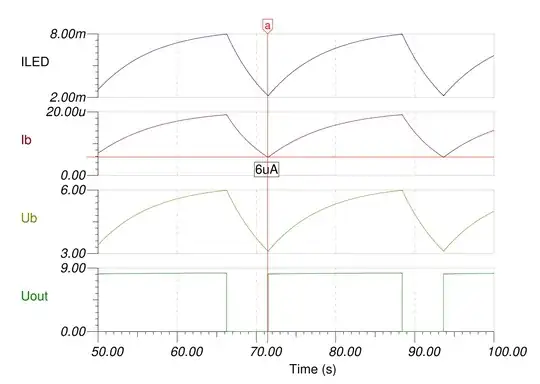
When voltage across C1 reaches 6V TH pin detect it and force Q to 0V. C1 start to discharge on (R1 ||BJT input resistor)*
When voltage across C1 reaches 3V TR pin detect it and force Q to 9V. C1 start to charge itself trough R1.
Current flowing in the led has more or less the following formula:
I=Vcap/R2
Vcap is going up and down and so does the light
*BJT input resistor is not infinite like a mosfet
- 126
- 5
Maybe it's easier to look that way. The base current of the transistor is not negligible compared to the charging / discharging current of R1. The base current slows down the charging of the C1 and accelerates its discharge. Otherwise, without a transistor, the duty cycle would be close to 50%.

- 2,156
- 4
- 5
