3

schematic

simulate this circuit – Schematic created using CircuitLab

N.B. I_D=KVov^2 without the 2

I’m really confused with this excercise, my problem is to calculate the A_v=v_out/vd and the cutting high frequency fH neglecting the parasites capacitors of the transistors (there is only C1) . I am confused because with the small signal circuit I can’t calculate the amplification of the differential amplifier because is asymmetrical and the source in not grounded.

I have Vo=-R1gmV_gs2 and I can’t find V_gs2

single ended differential

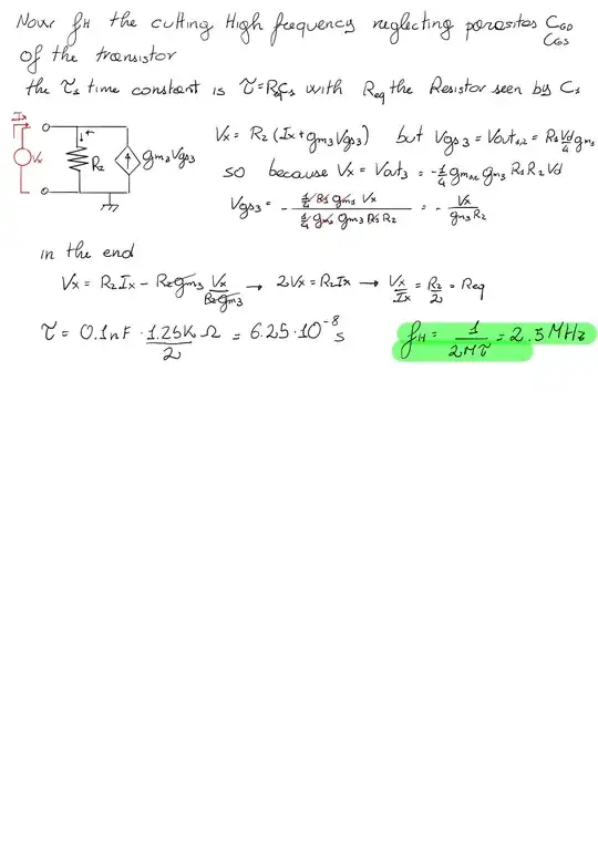
Here it is my solution

solution page 1

I have tried to use sovrapposition effect and obtained that Vgs_2= -Vd/2 but with a lot of effort obtaining a so clear result means that i'm not getting something about it. btw in the end i obtained A_v=-19.8 and fH=2.5MHz but i'm not sure they are correct

page2

  • How did you obtain FH = 16MHz? As for the gain, the Vgs is equal to Vd/2. Also, how did you get the A = 112.5? gm1 = gm2 = ?? and gm3 = ?? – G36 Sep 09 '20 at 14:10
  • gm1=gm2=4.4 10^-4 gm3= 8 10^-3 I tought there was no point ti show a mistaken calc but im going to add it as soon as possible – Sergio Piccione Sep 09 '20 at 14:19
  • Hmm, why I've got a different result? \$ g_{m1} = \sqrt{2KI_D} = \sqrt{2 * 1m * 50 \mu A} = 316\mu S \$ and \$ g_{m3} = \sqrt{2KI_D} = \sqrt{2 * 10m * 100 \mu A} = 1.41mS \$ – G36 Sep 09 '20 at 14:26
  • Why the 2 Is inside the Square root – Sergio Piccione Sep 09 '20 at 14:45
  • Btw im going to sent my solution, wait fifteen minutes – Sergio Piccione Sep 09 '20 at 14:46
  • What equation for ID current did you get from your teacher? 1 - \$I_D = K(V_{GS} - V_T)^2\$ or this one 2 - \$I_D = \frac{K}{2}(V_{GS} - V_T)^2\$ – G36 Sep 09 '20 at 14:49
  • The 1 - gm=2kVov – Sergio Piccione Sep 09 '20 at 14:50
  • Also notice that M1 and M2 are N channel MOSFET's not a bipolar transistor (NPN). And M3 is a P channel MOSFET, not a PNP bipolar transistor. – G36 Sep 09 '20 at 17:01
  • Yes correct, you dont know how many Times i wrote Collector instead of drain and viceversa – Sergio Piccione Sep 09 '20 at 17:02
  • Maybe this will also interest you: 1 https://electronics.stackexchange.com/questions/295771/i-o-resistance-of-common-source-mosfet-with-source-degeneration/295966#295966 2... https://electronics.stackexchange.com/questions/300044/find-the-gain-in-mosfet/300073#300073 3...https://electronics.stackexchange.com/questions/394295/small-signal-equivalent-circuit-mosfet/394365#394365 – G36 Sep 09 '20 at 17:05
  • Thanks! Very helpful, i m preparing for an exam and After a lot of excercises i'm starting to confuse things, i m gonna take a day of Just Reading excercises already solved – Sergio Piccione Sep 09 '20 at 17:20

1 Answers1

1

If the equation for a drain current in the saturation region (active region) looks like this:

$$I_D = K(V_{GS} - V_T)^2$$

Then the MOSFET transconductance is equal to:

$$g_m = \frac{dI_d}{dV_{GS}} = 2K(V_{GS} - V_T)$$

But if we substitute \$(V_{GS} - V_T) = \sqrt{\frac{I_D}{K}}\$ we will end with:

$$g_m = 2K\sqrt{\frac{I_D}{K}} = 2\sqrt{KI_D}$$

Now we can calculate the transconductance for your amplifier.

\$g_{m1} = g_{m2} =2\sqrt{1\text{m} [\frac{A}{V^2}]\times 50\mu A} = 447.2 \mu S \$

\$g_{m3} =2\sqrt{10\text{m} [\frac{A}{V^2}]\times 1.6\text{mA}} = 8 \text{mS}\$

Now the voltage gain. The \$M_3\$ voltage gain is:

$$A_{V3} = -g_{m3}R_2 = 8\text{mS} \times 1.25\text{k}\Omega = -10 V/V $$

And the voltage gain of a single-ended differential amplifier we can obtain using this small-signal equivalent circuit:
schematic

simulate this circuit – Schematic created using CircuitLab

$$V_O = -I_D * R_D = -g_{m2}*v_{gs2}*R_d$$

For this circuit \$v_{gs2} = -\frac{V_D}{2}\$ why?

Notice that becouse \$1/g_{m1} = 1/g_{m_2}\$ we have a voltage divider therefore.

KVL \$V_D = v_{gs1} + v_{sg2}\$ and notice that , \$v_{sg2} = - v_{gs2} \$)

$$\frac{V_O}{V_D} = \frac{g_{m2}*R_D}{2} = \frac{447.2\mu S * 18\text{k}\Omega}{2} = 4 V/V$$

So, the overall voltage gain is \$-10 * 4 = -40 V/V\$

As for the capacitor effect on the circuit, we need to find the pole frequency. and because \$M_3\$ is working as a common source amplifier we have this equivalent circuit:
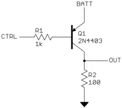
schematic

simulate this circuit

We can see that because the drain of a MOSFET in the saturation region has a property of a current source we see that the pole frequency is

$$F_H = \frac{1}{2\pi RC} \approx\frac{0.16}{R_DC_D}\approx\frac{0.16}{1.25\text{k}\Omega * 100\text{pF}} = 1.28\text{MHz}$$
G36
  • 13,642
  • 1
  • 18
  • 33