1

How to make the output of a ring oscillator look more like a rectangular wave?

I have designed a differential ring oscillator whose output takes the following form:

enter image description here

The output of a ring oscillator should be in a rectangular shape. But the output of my ring oscillator resembles no rectangular shape. How can I correct this problem?

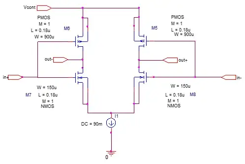
My design is a three-stage ring oscillator:

enter image description here

Each stage is a differential inverter:

enter image description here

I have tried the following tactics to make the output waveform looks more like a rectangular wave:

  1. Reducing the output capacitor
  2. increasing the source current in the differential inverters
  3. Increase the width of the transistors in the differential inverters

But all the above methods cannot yield the rectangular waveform. What other techniques I can use?

Thanks a lot.
Underdog
  • 367
  • 1
  • 11
  • 1
    The whole point of a ring oscillator is to run the inverters such that each one is contributing 60 degrees of additional phase shift beyond its natural 180 degrees from inversion. It is, inherently, going to be running flat out. There's just not going to be the high-frequency gain there to make the waveform square. The only way I can think to get a square wave out of one is to intentionally increase the capacitances, then follow it by a few stages of inversion to square things up. – TimWescott Sep 06 '20 at 23:10
  • Thanks for your reply. Do you mean I can increase the output capacitance such that each stage provides less phase shift, say 36-degree phase shift at each stage. In this case, I need a total of five stages to make a 180-degree inversion. And with more stages, the oscillator output can look more like a rectangular from. The main points are, (1) the more the stages in a ring oscillator, the more rectangular the output waveform would look like; (2) the more the stages, the less phase shift in each stage. Is my understanding correct? Thanks. – Underdog Sep 06 '20 at 23:28
  • 2
    That's getting beyond my knowledge; when I design circuits, its at the board level, not in silicon. I wasn't suggesting putting more gates *inside* the oscillator -- I was suggesting *following* the oscillator with some gates to square things up, but *only after* putting in more capacitance to slow things down. – TimWescott Sep 06 '20 at 23:52
  • 1
    @PhaeLeung Like Tim, this is outside my experience. But unlike Tim, he has a lot more experience than I do. That said, I do understand the circuit you provided. You will need to bring the signal out, somehow, and then apply gain and perhaps with positive feedback/hysteresis to square up the result. Since you have a current sink in each, would it be possible to increase the load seen by one stage (to pick off the signal) but also increase that particular stage's current sink to accommodate that requirement? (I don't like more stages as eventually this means harmonics are problematic, I think.) – jonk Sep 07 '20 at 00:11
  • 2
    @RussellBorogove It's about \$2\frac13\$ cycles in \$1\:\text{ns}\$, from my reading. Somewhat higher than a few MHz. – jonk Sep 07 '20 at 01:32
  • Thanks all for the reply. @jonk I think I have already implemented the positive feedback. Because each of the three stages already provides 60-degree phase shift. Otherwise, the oscillator would not oscillate. Also I have also tried to increase the sink source, but the shape does not improve. – Underdog Sep 07 '20 at 01:34
  • 1
    @PhaeLeung No, I meant after the "pick off" of the signal. Not within the ring, itself. I was just wondering if you could run one of the stages "a little hotter" than the others and use the extra drive current to support bringing a small signal outside the ring. (It seems like you'd need to do this anyway, as what's the point of having a ring if you don't use it? So I'm probably not seeing the whole picture of your question.) – jonk Sep 07 '20 at 01:35
  • @jonk I am sorry. Could you please explain what do mean by "pick off of the signal"? I don't quite understand. – Underdog Sep 07 '20 at 01:37
  • 1
    @PhaeLeung Nothing more than Tim meant when writing, *"... then follow it by a few stages of inversion to square things up."* You'd need an additional pair of capacitors to tap in between stages and bring it out, as I imagine it. Perhaps we are misunderstanding each other, though. None of this is about having a square wave within the ring, itself. You've already got a fantastic ring going there. – jonk Sep 07 '20 at 01:38
  • @jonk doesn't "follow it by a few stages of inversion" mean more stages? – Underdog Sep 07 '20 at 01:40
  • 1
    @PhaeLeung No. I think that would be "not so good" as it increases the energy and gain available for higher frequency harmonics that you should not want inside the ring itself. I actually ***like*** what you have there. It's almost beautiful to me. Very nice. I'd leave that alone. If I wanted a square wave from it, I'd look to tap into the ring and bring out a signal I could use and shape into a square wave with a completely separate circuit. I would in no way mess up what you already have. It's nice to my eye. – jonk Sep 07 '20 at 01:42
  • @jonk Thanks. I think I understand now. You mean I can take this output of this oscillator and use other circuit (e.g. a clipper circuit) to make it square like. Is my understanding correct this time? Thanks again for your patience. – Underdog Sep 07 '20 at 01:49
  • 1
    @PhaeLeung Yeah, that's more along the lines of what I'm thinking. But if you load down one of the stages with added capacitance it will not perform the same. To repair that, you need to work out how much added capacitance you need to "pick off the signal" and then adjust the current sink for the stage driving that extra-loaded node pair accordingly. If you double the capacitive load, then double the current sink so that the speed is about the same. – jonk Sep 07 '20 at 01:53
  • 1
    @PhaeLeung Of course, a ring oscillator runs somewhat unpredictably based upon details of the resulting cut die from the wafer. Which is another issue your circuit doesn't appear to deal with, at all. That may be a problem. One solution in my mind is to arrange one of the stages with a variable current sink that can be tweaked to get calibrate the oscillation frequency. But I'm just a hobbyist. So keep in mind my limitations. – jonk Sep 07 '20 at 01:54
  • @jonk I think I understand it. If I want to use additional circuitries to make a square-like waveform, I need to reduce the capacitance of each stage such that the phase shift of each stage is reduced. It is because the additional circuitries may lead to further delay. And the oscillator should have 360-degree phase shift around the loop to satisfy the Barkhausen criteria. – Underdog Sep 07 '20 at 02:01
  • First thing you should try is simply another inverter that is *outside* the ring but fed from it. Logic is designed with excess gain in the transition region so that the output will hopefully be squarer than the input. In the real world, you also have to keep in mind that probing fast clocks without distorting them is not easy; and affordable instruments may have limited bandwidth - see for example https://electronics.stackexchange.com/questions/520274 for someone having a problem with a physical circuit. – Chris Stratton Sep 07 '20 at 22:59
  • And where did your plot actually come from? It appears to have a number of sparsely placed points on it filled in with an interpolated sine which assumes *band limiting*. Much as with the limited capability of the scope in the question of the comment above, that plot may not be representing the true situation, but only those insufficient sample reconstructed under an *assumption* of no high frequency content, making the wave more sinuous than it may actually be. – Chris Stratton Sep 07 '20 at 23:01
  • It is generated by PSPICE simulation. I set the max step size in the transient analysis at 1us, which I know is a low resolution. I intentionally set a low resolution to save some simulation time. Do you mean the output waveform could be more square like if I increase the resolution? – Underdog Sep 07 '20 at 23:06

2 Answers2

1

Easy peasy lemon squeezy. Just add a comparator that biases to the midpoint of the signal. They are basically op amps that run pole to pole. Here is the example circuit on the output.

schematic

simulate this circuit – Schematic created using CircuitLab

Note that R1 and C1 should adjust according to how often, if at all, the DC bias of your signal changes. If however your signal is AC coupled and has no DC bias of any kind then you can eliminate R1 and C1 and put ground directly to the positive of the comparator.

Also keep in mind the comparator will output its square wave rail to rail, so you either need to use positive and negative poles to get a ac-coupled output or you need to put an appropriate capacitor on the output to reject the DC bias if that is what you want.

Here is the output from the simulation of the above circuit showing the conversion of the input sine wave into a square wave.

enter image description here

1

If you want to preserve the phaseshifts of each stage, then load EACH stage with the identical and additional tap-off circuit.

Avoid positive feedback in the first stage of the tap-off circuit, because any snappy/abrupt edges will inject charges onto the RingOscillator capacitors.

Have that tap-off be an over-driven differential stage, with no feedback. Then the downstream circuit in each tap-off can be a positive-feedback circuit to provide the 50 picosecond edges you want.

=================================

regarding need for square edges: 10pF and 10picoSeconda at 3.3 volts will require

  • I = C * dV/dT = 10pF * 3.3v/10pS ==3.3 amps
analogsystemsrf
  • 33,703
  • 2
  • 18
  • 46
  • Thanks all gain. Please excuse me for a follow up question. In a real application, is it necessary for a ring oscillator to have a nearly square waveform? For example, if the ring oscillator is used as a clock, I think it is necessary that the output waveform must be nearly a perfect square. This is why I insist to obtain a square waveform. Thanks a lot. – Underdog Sep 07 '20 at 06:12