6

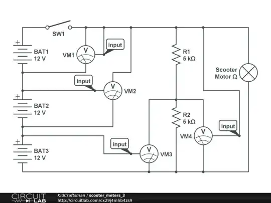
I bought some small voltmeters hoping I could use them with my kid's Razor dirt bike. The bike uses 3 12v lead-acid batteries in series to provide 36 volts to the motor. Ideally, I'd like to use the voltmeters to measure total voltage of the batteries in series, as well as the individual voltages of each of the batteries. I'd also like connect the voltmeters to the power switch, so they only measure voltage when the bike is powered on.

The working voltage of the voltmeters is 4 to 30v, and they can measure 0 to 100v.

The voltmeters have 3 wires. I ran the positive wire to the power switch, I ran the ground to the ground of each battery, and ran the measurement wire to the positive terminal of each battery. This seems to work fine for the first 2 batteries, because they are powered by 12v and 24v. The voltmeters for the last battery and the overall system end up getting 36v, which is too much for my tiny voltmeters.

The power switch is a single throw dual pole switch. Is it possible for me to power the voltmeters with 12v and use them to measure the system as described above?

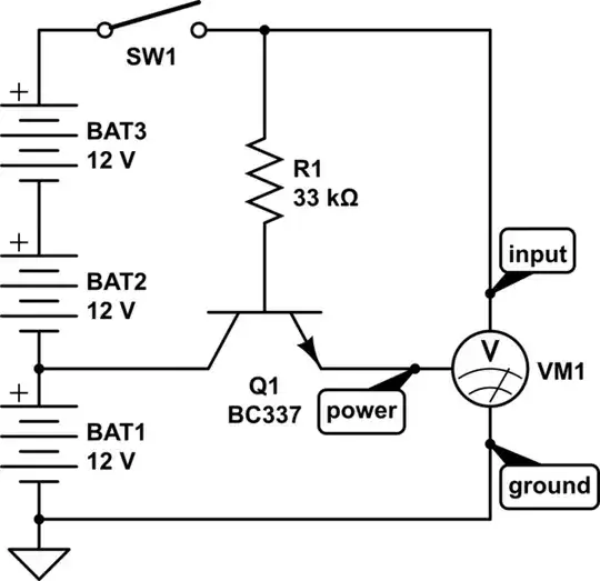
UPDATE based on great feedback. I didn't know about reducing voltage with a resistor ladder. This is basically what I have now, just without the resistors. Will this work? I was afraid it may cause a short, because it seems like the batteries are both in series and parallel this way. CircuitLab Schematic x29j4mhb4zs9

UPDATE - using 2 470ohm 5W resistors worked to divide the voltage, but the resistors generated too much heat. I measured 190 and rising after a few minutes. That seems dangerous. I'm going to drop back to 1 voltmeter powered by one battery, measuring all 3, and tied to one of the poles in the DPST switch.

  • If the three 12V batteries are always connected and used in series, I see no need to measure each battery individually. I would threat the battery as one 36 V battery. Measuring each battery separately only complicates things (it is possible but you do not appear to have enough experience to figure out how to do this). – Bimpelrekkie Sep 02 '20 at 09:06
  • Simplest solution: get a (switching) voltage regulator module to make 12 V from the 36 V. Get one that can withstand 42 V at the input as a fully charged 12 V Lead acid battery can go up to 14 V. Use that regulated 12 V to power the voltmeter module. As the voltmeters can measure up to 100 V at the measurement input, you can connect that directly to 36 V. – Bimpelrekkie Sep 02 '20 at 09:08
  • @Bimpelrekkie, you have accurately assessed my experience level. Is it possible to power a single 3-wire voltmeter from one of the 12v batteries, but use it read the voltage for the 36v system? – KidCraftsman Sep 02 '20 at 09:40
  • 1
    You have suggested that your voltmeters can measure 0 to 100V. Can your voltmeters measure negative voltages? If so, there's a simple solution - use the **middle battery** in the string to power all the voltmeters. Only one will be required to measure the -ve voltage (-12V). – glen_geek Sep 02 '20 at 12:33
  • unfortunately, they don't measure negative voltage – KidCraftsman Sep 02 '20 at 19:19
  • That's one more wire than a voltmeter needs. Are you aware of the existence of analog voltmeters that power their movement off the load they are measuring? They draw extremely little power, certainly far less than the batteries' self-discharge rate. – Harper - Reinstate Monica Sep 02 '20 at 20:00
  • @Harper-ReinstateMonica I'm trying to use the voltmeters I already bought... and cut holes for. – KidCraftsman Sep 03 '20 at 14:58
  • 1
    Re: the update. It looks reasonable, but you may need to tweak R1 and R2 to allow enough current through to power both meters. If the current draw of the meters is reasonably constant, then it's easier. R1 and R2 don't have to be equal. – Simon B Sep 03 '20 at 16:17
  • @simon-b Thanks. The current draw for each meter is < 20mA. – KidCraftsman Sep 03 '20 at 17:08
  • 1
    OK, a bit of a rough calculation, but if we assume 2x20mA, and want to drop 18V across R1, then that comes out at 450 ohms for R1. Use a resistor rated 1 watt or more, as it will get quite warm. R2 could be 1k ohm, just to avoid the voltage on the meters floating too high if they are drawing less current. – Simon B Sep 03 '20 at 20:32
  • @SimonB I was planning to use 1watt 1.5k resistors. Google told me I could find the requisite power by using the following formula: (Voltage / Resistance) x Voltage. I'm not familiar with how to ensure the values for R1 and R2 will allow enough current to power the meters, or what would cause the voltage to float too high. If you could point me in the right direction to learn about this, I would really appreciate it. – KidCraftsman Sep 04 '20 at 12:10
  • 1
    There's no way you're going to get 40mA through a 1.5k resistor. Ohms law says that the voltage across R1 will be V = IR = 0.04 x 1500 = 60V. That's more than your supply voltage! I used R = V/I = 18 / 0.04 = 450 ohms. – Simon B Sep 04 '20 at 18:53
  • facepalm... thanks for helping me understand how to apply Ohms law in this case. I ordered some 5W 470 ohm resistors to try this out with. – KidCraftsman Sep 08 '20 at 11:36

4 Answers4

4

Here's one way to power the voltmeter from the bottom battery while measuring the whole string.

schematic

simulate this circuit – Schematic created using CircuitLab

to measure the individual voltages is trickier.

schematic

simulate this circuit

3

You can do this with inexpensive two 5VDC or 12VDC DPDT relays and a buck module (eg. the ubituitous LM2596 modules) as shown.

Set the buck regulator output voltage to the relay voltage.

I've shown it with a momentary switch to actuate it so it won't drain the batteries continuously.

schematic

simulate this circuit – Schematic created using CircuitLab

Note that if any of the batteries becomes 'open' some of the meters may be damaged if they don't have reverse polarity and overvoltage protection.

Spehro Pefhany
  • 376,485
  • 21
  • 320
  • 842
3

Old-timer here. You're making this harder than it is.

The reason you're making it hard is that you insist on using powered meters. They make simple, unpowered meters that simply power themselves on the voltage they are measuring. They draw little enough that your far bigger problem will be battery self-discharge. But even then, turning them off is easy.

But it's easy with powered meters too; we'll just need a DPST relay and in one case we'll need a voltage divider out of 2 resistors.

First, for the "whole pack" meter we do exactly the same thing - go from bottom battery rail to switched side of the switch.

But for the powered meter, won't that be overvoltage? If you're averse to getting a better meter, then simply add a resistor ladder - a size X resistor from top rail, to meter power supply and a size X resistor to bottom rail. Start with a high value resistor like 10K, and if the meter refuses to power up, add lower value resistors in parallel (both top and bottom at once) until you find a happy number. When you're testing, it's easier to lower resistance than raise it, that's why I say start with a high value.

Why not 1 resistor for the resistor ladder? Because we can't count on the voltmeter behaving like a resistor (having the same impedance in any mode).

For the 3 per-battery meters, we make a "meter ladder" as it were. And we tie the meters ladder to the battery ladder. Since you are worried about the current draw of the meters, we need a DPST relay interrupting the ladder (the top of the ladder is already interrupted by the power switch).

If powered, these voltmeters simply take from the voltage they are measuring.

schematic

simulate this circuit – Schematic created using CircuitLab

I have no idea what's up with the editor's numbering of meters and relays.
The resistor ladder is only there for a powered meter; values unknown TBD. Consider analog meter or meter with higher supply in.
The relay can be eliminated if meter draw is too small to care about (compared with natural battery self-discharge).
The switch could be replaced by 3PDT switch to eliminate relay.


By the way, I gotta put this in here... OP took my resistor ladder concept and found a way to eliminate the relays. This is really good IMO. Although note that depending on the meter, there may be 24x7 leakage through the meter's measurement section, as Sphero discusses in a comment to another answer.

  • I've already cut holes in the body of the dirt bike, and installed the cheapo voltmeters. Personally, I think they look really cool. The problem is, they don't work... and I'm worried I may start a fire. @Bimpelrekkie is not wrong about my lack of knowledge and understanding. I didn't realize there were so many ways to solve this problem, and honestly... this is kind of exciting. I want to learn more, and I really appreciate everyone's help on this. – KidCraftsman Sep 03 '20 at 01:17
  • In this scenario, where would I include the dirt bike motor powered at 36v? – KidCraftsman Sep 03 '20 at 01:25
  • @KidCraftsman There ya go. Schematic updated. – Harper - Reinstate Monica Sep 03 '20 at 04:12
  • [![CircuitLab Schematic q82r3cp83t57](https://www.circuitlab.com/circuit/q82r3cp83t57/screenshot/540x405/)](https://www.circuitlab.com/circuit/q82r3cp83t57/scooter_meters/) – KidCraftsman Sep 03 '20 at 14:42
  • I was afraid this would cause a short. Seems like the batteries are both in series and parallel this way. – KidCraftsman Sep 03 '20 at 14:43
  • @KidCraftsman yes, but it will be hard to use and the rightmost meters are redundant. – Harper - Reinstate Monica Sep 03 '20 at 14:43
  • doh. I didn't get the diagram quite right. Trying again [![CircuitLab Schematic v82794p27r6e](https://www.circuitlab.com/circuit/v82794p27r6e/screenshot/540x405/)](https://www.circuitlab.com/circuit/v82794p27r6e/scooter_meters_2/) – KidCraftsman Sep 03 '20 at 14:56
  • @KidCraftsman Oh, that's much better. Very well done, you've eliminated the relay and got it done with passives! – Harper - Reinstate Monica Sep 03 '20 at 15:28
  • Thanks, Harper - Reinstate Monica. I'm going to try the solution I arrived at based on your design. I really appreciate the help. – KidCraftsman Sep 03 '20 at 17:14
2

schematic

simulate this circuit – Schematic created using CircuitLab

Here is a way to do it using one voltage regulator. Each meter is fed a supply not more than 24V above its common negative terminal.

Simon B
  • 18,609
  • 1
  • 29
  • 55
  • 1
    You might want to add a diode in series with the meter power leads (VM1 and VM2 in particular) if the modules don't have them and even with that, there will be a bit of continuous drain from the measurement input dividers on VM1 and VM2 and VM3 even with the switch off, but only BAT1, and BAT2, not BAT3. – Spehro Pefhany Sep 02 '20 at 13:39