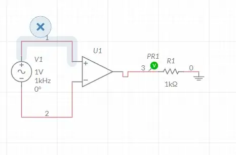
I want to know what is the ideal circuit to measure open-loop frequency response and why?I have seen the typical open-loop frequency response curve for an op-amp a lot of times. But when I try to plot it for my circuit simulation even though it resembles the shape, it varies a lot with the input signal. I am simply sending a small AC signal with no feedback and plotting output. What will be the ideal input AC signal to plot it assuming I want to use this later for Differentiator design assuming I want to use an inverting op-amp for it.

- 41
- 6
-
1Check out this video from TI. The whole series of videos are fantastic. But they have a great way to simulate the Aol curve to verify your op-amp model as well as simulating the loop gain of your final circuit for stability analysis. Google around for other TI app notes on this, they have good stuff. https://training.ti.com/ti-precision-labs-op-amps-stability-spice-simulation – guitardenver Aug 30 '20 at 04:45
-
1You can take a look at an answer I wrote [here](https://electronics.stackexchange.com/questions/297189/determining-open-loop-gain-of-an-opamp-in-ltspice/297275#297275) where I used a loop to exactly bias the op-amp at the desired level. This helps forcing the op-amp output to the output voltage of your choice without resorting to trial and error via the manipulation of µV-size input sources. – Verbal Kint Aug 30 '20 at 07:26
-
@VerbalKint can you please tell me what is the other op-amp like symbol in that answer, I am using multisim and not LTSpice. – vikas sajanani Aug 30 '20 at 15:41
-
1The other symbol \$E_1\$ is a simple voltage-controlled voltage source. If you affect it with a gain, it becomes an ideal op-amp. – Verbal Kint Aug 30 '20 at 16:50
1 Answers
Drive with 1 micro volt (swinging +- 0.5 micro volt above and below ground), and ground either vin-, or vin+ pin.
Try an AC simulation, from 1 Hz to 100 MHz. Log, 10 steps/dcades.
Examine the dc conditions, observing the Vout is very near 0 volts.
If not, then add a dc feedback , to ensure the opamp is biased as an amplifier:
apply the +-0.5uV only to the Vin+, other pin of source to ground.
connect Vin- to ground, thru a 1ohm resistor
attach th efeedback, by using 100,000 ohm resistor from Vout to Vin-
Now examine what you have on the nodes.
==================================
The 2nd circuit has large closed loop gain, yet the opamp only provides high gain at very low frequencies.
Try with 100 Hz in, 1uv, symmetric around ground.
And try with 100,000 Hz in, 1uv, symmetric around ground.
- 33,703
- 2
- 18
- 46
-
-
Dear @analogsystemsrf , I tried adjusting the circuit and initially my output was very low, I tried adjusting input and was applying 20 micro volts while the output was not hitting rails at about 2V peak to peak. However, I don't know what is the validator. How do I know I have the right frequency response. With the second circuit you mentioned, if I connect a feedback the loop becomes closed, why is this useful for measuring open loop response. I am sorry if this questions seem to simple, but please bear with me. – vikas sajanani Aug 30 '20 at 16:13