7

I have an ultrasonic emitter, and two ultrasonic receivers. When the emitter emits a pulse, the receivers get the signal at different times. I am only interested in the difference between the two reception times.

At first, I was thinking of using a microprocessor, measuring individual arrival times, and then taking the difference. Taking two absolute measures when only a difference is required feels somewhat unnecessary, and may add inaccuracies.

Is there a way to measure pulse time differences in hardware, i.e. analogically? Would this be advisable?

Randomblue
  • 10,953
  • 29
  • 105
  • 178
  • 2
    It depends on what you want to do with the result, and whether or not that result is more useful as an analog signal or a digital value. Why do you say taking the difference with a microprocessor is "unnecessary"? – Dave Tweed Dec 20 '12 at 20:04
  • @DaveTweed: What is unnecessary is taking two absolute measures, since I'm only interested in a difference. – Randomblue Dec 20 '12 at 20:50
  • I haven't heard Analogic for 15 years ( termed coined by a fraud cam finger authenticator for the military say the 3D cam image was 3D vs 2D digitized linear scanner ) On delta echo measurements you want to consider high speed differential amplifier to digitize. Choose slew rate and BW according to requirements. I prefer ECL comparators for slicers as the prop delay is matched within a sub-nanosecond. I can't recall the p/n since I used one last >20yrs ago – Tony Stewart EE75 Dec 21 '12 at 01:09
  • I did design a Doppler tracking telemetry system using two RF antenna , sub-carrier OCXO mixed with ground station OCXO to determine azimuth rocket tracking in the 70's. THat was before ECL and I used bipolar slicers fraught with asymmetric delays and slew rates.. but worked for ns resolution. 1st hit... something like this http://html.alldatasheet.com/html-pdf/122648/ONSEMI/NBLVEP16VR/219/1/NBLVEP16VR.html – Tony Stewart EE75 Dec 21 '12 at 01:10
  • or simpler with this MC10EP29 << then use a time interval counter to measure the pulse width in hardware. or use PLL or use sawtooth sampling phase detector into S&H to quantize image. – Tony Stewart EE75 Dec 21 '12 at 01:19
  • What resolution do you need? a few degrees of ultrasonic self resonant period? or many cycles in duration? I did not see what range you are using 1~10MHz ? – Tony Stewart EE75 Dec 21 '12 at 02:28

4 Answers4

3

Use a so called TDC, e.g. the acam-gp21: http://www.acam-usa.com/GP21.html. It even has an example for ultrasonic measurement in the manual.

Tom L.
  • 7,969
  • 1
  • 19
  • 34
2

You could do it in hardware with some comparators, a fast clock, a couple of counters and a subtracting circuit...

You could also use the comparators with some op-amps configured to integrate, then subtract the difference in voltage level between the two integrators, then use some means to convert that voltage difference into a meaningful time value.

There are probably some other creative ways of doing this but it seems like a race to an ever-more elaborate Rube Goldberg machine. This is the kind of application a small micro excels at, and depending on your implementation, would be far more accurate at than an analog circuit requiring precision components and careful tempco planning.

akohlsmith
  • 11,162
  • 1
  • 35
  • 62
2

A few MSP430 devices have a peripheral called Timer D that has 4ns time period and I've seen it used for these kind of applications. See MSP430 with Timer D

It should simplify development significantly.

Gustavo Litovsky
  • 7,619
  • 3
  • 25
  • 44
  • Thanks. Do you know if ARM processors have a similar thing? – Randomblue Dec 20 '12 at 20:48
  • I don't know of any ARM processor with that kind of peripheral since it's very specific. You then have a few options: Implement this in FPGA or a high frequency processor, or even with discrete components. MSP430 was a relatively easy and inexpensive solution. – Gustavo Litovsky Dec 20 '12 at 21:13
  • Realistically even a 1 uS period is likely to be sufficient for most purposes - that's a 1/3 of a millimeter in air, and 5mm in iron, and if that's not good enough timers clocked >10 MHz are available from numerous sources. – Chris Stratton Dec 20 '12 at 21:43
  • Yep. 4ns would be probably overkill. 1.3um or so (probably less due to other things but still, very fast) – Gustavo Litovsky Dec 20 '12 at 22:11
  • it's just a timer with a capture input. Nothing earth-shattering but very useful for this kind of thing since it really relaxes the micro's requirements. – akohlsmith Dec 20 '12 at 23:31
2

From your previous post I know that you will going to use a 400ST/R100 ultrasonic transducer. The main problem with these transducers that they are narrowband. Look at received signal (The first measuring results with oscilloscope) http://www.technik.dhbw-ravensburg.de/~lau/ultrasonic-anemometer.html maybe now you will understand the problem.

TOF detection methods

1) Reference level crossing, problem - it's depend from received signal level, if you going change distance it's will be a problem.

enter image description here

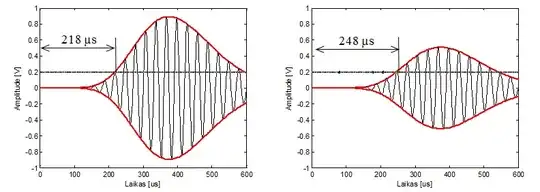
2) Zero crossing or signal max possition finding requires signal digitization. To find max possition for such signal is hard because it's have a flat top (look at signal envelope).

3) Correlation or L1, L2 norms calculations. To get max possition of correlation accurately use parabolic interpolation. If you calculate correlation between received signal you will get something like this. (It's autocorrelation of received signal after transmiting three 40KHz pulses)

enter image description here

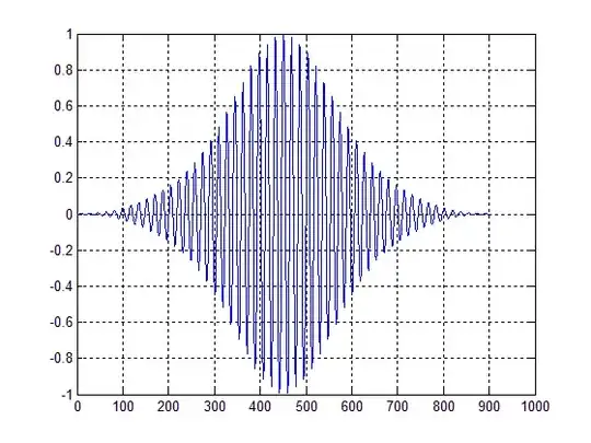
As you see the main problem of correlation is side lobes. If you change excitation signal to Chirp side lobes will be lower. Despite these side lobes I was managed to get 0.9ns standar deviation of TOF, with equipment I mentioded in your previous post.

Witch method to choose? It's depends of accuracy you need.