2

I recently came in to a voltage meter 0-5v. I want to use it with esp8266 as a humidity display for my weather information station.

the exp8266 model I'm using (wemos/nodMCU) is 3.3V, I can use PWM to set the needle, but it won't use the full range of the meter. I need to scale the voltage up to 0-5v.

enter image description here

So, after reading a bit I decide what I need is an op amp. I order one that seemed like it would work from the data sheet... but I don't really know how to set it up.

enter image description here

https://cdn-shop.adafruit.com/datasheets/tlv2462.pdf

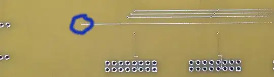
Here is how I've hooked it up.

enter image description here

futurebird
  • 652
  • 6
  • 14
  • 2
    It won't work like this. Your amplifier circuit needs a bit more components (2 resistors at least). What you need is a non-inverting amplifier with ratio 5/3,3. You will also be limited because the op amp is limited to max 4,9V in output when supplied with 5V. – Wheatley Aug 22 '20 at 01:38
  • 4.9 will be good enough. I can adjust the scale to match it. where can I find out about where I need to put those other components? I'd also like to know WHY I need them so I can learn to do this myself. – futurebird Aug 22 '20 at 01:55
  • Why have you placed a tag called "741-opamp"? – Andy aka Aug 22 '20 at 07:21
  • I just placed the general op amp tag... that might be a mistake.. – futurebird Aug 22 '20 at 12:42

2 Answers2

4
  • meters of this size are around 1mA full-scale meaning 1k Ohm/volt.
    This is class 2.5 or 2.5% accuracy shown in the fine print.

A primitive yet simple and elegant solution is to change the internal resistance to 66% of the total value of resistance that is full-scale current with a 1% resistor.

schematic

simulate this circuit – Schematic created using CircuitLab

Disassemble measure required current for full scale @ 3.3V and add to R2 as shown then reassemble in reverse.

Tony Stewart EE75
  • 1
  • 3
  • 54
  • 182
3

You can do something like this:

schematic

simulate this circuit – Schematic created using CircuitLab

R3 & C1 form a low-pass filter with cutoff f = 1/2piRC ~= 1.6Hz. Ceramic X7R is okay for this part.

R1 and R2 set the gain, and are chosen so that R2/(R1+R2) ~= 3.3V/5.0V, are high enough not to significantly load OA1 output, and are standard E96 1% values.

If you replace R1 with R4+RV1 you can trim the output sensitivity.

I suggest using somewhat less than the 5V angle (maybe 90-95%) and trimming the full scale in with the pot if you go this way.

OA1 should also have 100nF bypass capacitor across the power supply pins near the chip (not shown).

Spehro Pefhany
  • 376,485
  • 21
  • 320
  • 842