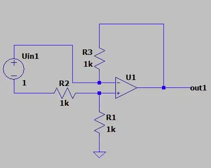
First circuit
It resembles the classic op-amp differential amplifier but without one resistor. It is interesting that all its components - R1, R2, R3, and Vin1 are connected in series to the op-amp output. So, the same output current flows through them.
Note the two op-amp inputs are equal and floating. So, when the input voltage varies, both they vary (a common-mode signal).
The op-amp will try to set zero voltage between its inputs. So the input "real voltage source" (Vin1 + R2) will be virtually shorted and Vin1 = VR2. This current flowing through R2 will be I = Vin1/R2. The same current flows through all resistors... and the output voltage Vout1 is....... Only, what is the point of this?
It would be interesting to understand the mechanism of the H&H "virtual short" between the op-amp inputs because there are no good explanations for this phenomenon. What gives the inputs short is the network of three elements in series - R1, Vout and R3. It behaves like a "piece of wire" with zero resistance because the op-amp output voltage neutralizes the total voltage drop across R1 and R3 (Vout - VR1 - VR3 = 0). Saying it in a more attractive way, the op-amp output acts as a negative "resistor" with resistance -(R1 + R3) that compensates the total positive resistance (R1 + R3) and the resulting total resistance is zero (R1 + R3 - R1 - R3 = 0).
Second circuit
The second circuit is simply an inverting ampifier with R1 = R2 = 1 k. Only there are two strange things - Vin2 is floating and R4 is between the load and ground (in series to the load). Both they do nоt make sense.
The ground
I'm only interested about why I can't choose the ground arbitrary on this schematic.
The ground has two functions (meanings). First, it is a common point for all devices (source, amplifier, load); so it sinks all currents (if negative). Second, it is a reference point when measuring the voltages inside circuits (where you connect the black probe of the voltmeter).
In your circuits, the ground is the middle point of the power supply (or the middle point of two voltage sources in series). Since the output voltage should be negative, the current will flow through the negative supplying voltage source. In the first circuit, the input current will flow through R1 while in the second circuit this current will not flow through this resistor (named R4 here). Now the load current will flow through R4 (if there is a load connected).
Simply speaking, the ground is just one of the power supply terminals (positive, negative or middle). So, when changing its place, you connect this terminal to a different point of the circuit... and this is already a different circuit.
So, the conclusion is: You can arbitrary choose only the reference point for the voltage measurement but not the common return point since this changes the current path and the circuit itself.
Applications
I'm aware that those circuits aren't super useful.
Still there is a reasonable application of the first circuit... It is a "unbalanced differential amplifier" relative to the common-mode signal but this does not matter here because the input source is floating. There is no problem to use it with a differential input voltage what Vin1 is.
What is more interesting is that this amplifier can be single-supplied. When the input voltage increases, both op-amp input voltages increase as well (acting as a common-mode input signal). Thus they stay somewhere between the rails as though the op-amp is biased.
I have seen this trick of an "auto biasing" in the circuit of a photo diode amplifier below in the H&H bestseller (see my answer). The photodiode acts as the "Vin1 + R2" network in the first OP's circuit.