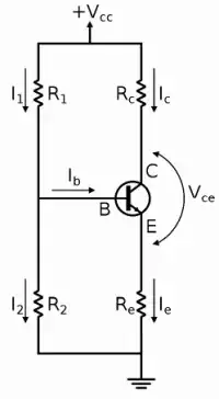
I am studying BJTs and I came across this configuration. My book applies Thévenin equivalent to the base and I do not understand how it does that, it does not make sense as there is base current to take into consideration. I kind of know about Thévenin equivalent circuits but I do not really understand how it works when I think of solving the same circuit by normal means(node analysis, KVL etc) I just cannot. Can you explain what is going on like I am an idiot?
Asked
Active
Viewed 182 times
1
-
I shrunk it from a large wafer size to something smaller than my face. The most important part of your studies is to learn how to learn by choosing the right "Key words" to help yourself. Then you won't feel like an idiot, but rather a scholar. https://electronics.stackexchange.com/search?q=Th%C3%A9venin+equivalent++bjt – Tony Stewart EE75 Aug 08 '20 at 19:14
-
1see this answer https://electronics.stackexchange.com/questions/471906/calculation-of-base-current-and-what-decides-the-current-through-collector-emitt/471923#471923 – G36 Aug 08 '20 at 19:16
-
For an intuitive analysis, think of the Base voltage,Vb as a water tap to control the Emitter voltage,Ve (1 diode drop down) and thus Emitter current=Ie=Ve/Re (0.65V down from the Base if Ic= 1mA,) otherwise 0.7 is a nice odd number for Vbe. You can view the Base impedance as ~ hFE*Re – Tony Stewart EE75 Aug 08 '20 at 19:18
-
The Emitter, Ie=Ib+Ie, combines both Base , Ib and Collector current, Ic so we say Ie=(hFE+1)*Ib but since hFE the base current gain varies so much (>50%) and when not saturated is so large, we truncate hFE+1 to just hFE. Actually it is Vbe that controls Ic, but that's not needed here to figure out Vbe precisely. We can assume a reasonable value when the Re is included to make Vb more controlled by R1&R2 – Tony Stewart EE75 Aug 08 '20 at 19:30
-
[Related ?](https://electronics.stackexchange.com/a/512288/238590) – AJN Aug 08 '20 at 19:38
