7

I'm using a 850nm IR LED (spec sheet), and in order to extend my battery life, I'd like to make the LED blink (UF 1.9 V, IF 100 mA).

I found a couple of links 1, 2, 3 but they either a) require two LEDs that blink in alternation, or a bunch of resistors that will most probably just drain my battery even quicker (will they?).

Therefore my question:

What's the

  • most simple
  • energy efficient
  • smallest possible (ideally not bigger than the battery & LED)
  • ideally operated with 3V or less.

circuit to make an IR LED blink?

EDIT:

  • I'd like to blink the LED 10 to 30 times per second. But We can start with 2 to 5 times.
  • the LED should be on for 10ms (at least) or 100ms (at most). Depending on blinking frequency.
  • I'm trying to make the circuit as small as possible (size and complexity) cause I wanna use it for a tracking device.
  • I'm powering the LED with a 3V CR2032 battery and I was hoping I could extend the battery life by making the LED blink instead of having it on all the time.
  • I can currently run the IR LED with the CR2032 battery for 4 hours. Extending that time to 8 or maybe even 12 hours would be great.
memyself
  • 143
  • 1
  • 1
  • 7
  • 3
    The 555 timer one, with large value resistors in the voltage divider, is probably the best. It might need an extra transistor to handle the 100ma. – pjc50 Dec 17 '12 at 15:04
  • @pjc50 can you be more specific? I really have no clue how to pick the right resistors. I'm also wondering whether large resistors will drain my battery more quickly - will they? – memyself Dec 17 '12 at 15:51
  • 1
    It might be useful to know how often do you need your led to blink, and how long should it stay on. And you might wand to add further details about your specific project. – Vladimir Cravero Dec 17 '12 at 16:15
  • @VladimirCravero I've added further details to the end of my posting. – memyself Dec 17 '12 at 16:49
  • doesn't an IR receiver typically require a roughly 30kHz pulse on the transmitter to detect? I could be completely wrong, but that rings a bell for some reason... – vicatcu Dec 17 '12 at 17:01
  • @vicatcu, I think that he is not using normal 36kHz receivers, in my sense of tracking you need a camera. memyself, is the blink duration significant? if 10ms is okay for you I'd keep that one, the less the led is on, the less the battery is used. Same thing about blinking frequency. The 555 is not a bad idea, you should do some calculations on power consumptions and check if you meet your minimun desired duration. – Vladimir Cravero Dec 17 '12 at 17:08
  • @vicatcu I use a 30Hz IR camera to detect the IR signal. Therefore 30Hz or at most 60Hz should be enough to see the signal. – memyself Dec 17 '12 at 21:22
  • Different approach to longer battery life is a "Joule Thief", which allows you to drain your battery far beyond the point to where you would normally replace it. https://en.wikipedia.org/wiki/Joule_thief – jippie Jan 06 '13 at 14:40
  • This would be easy with an Arduino. [ducks] – Phil Frost Jan 06 '13 at 16:37
  • 1
    Wait, how are you getting 100ma from a cr2032? How long do you expect to power it at that rate anyway? The cr2032 has a nominal current capacity of 250ma... – Passerby Jan 06 '13 at 21:22
  • 3
    555's operating current is too large to be powered by a CR2023. If you really want to use a 555, instead use 7555, a CMOS variant of 555 timer. – Chetan Bhargava Jan 06 '13 at 23:42
  • 3
    The comment above is right. "555" and "energy efficient" are like a fist and a face. When they meet, nothing good happens. – Christoph B Jan 07 '13 at 11:09
  • @memyself can you give more detail about the desired blinking? 2-30 Hz is quite a large range. What confuses me is that at the upper end of this range, the LED might as well be blinking at 2 GHz. Anything approaching the frame rate will appear to be "always on". So, do you want to blink because you want it to be intermittently visible, or do you want it to blink because you want to save power, yet still have it be visible in each frame? – Phil Frost Jan 07 '13 at 14:00
  • 1
    @memyself: also, what do you mean by "simple"? Do you mean low component count? Do you mean simple to understand? Do you mean simple to assemble? Simple to purchase? Do you want to rule out all ICs? What about microcontrollers? – Phil Frost Jan 07 '13 at 14:02
  • @memyself - I am curious about your application - capturing flashes with a camera is a complicated way of doing things, and you need to be aware of the issues (Nyquist frequency / aliasing). Also worth noting that most cameras have an artificial shutter effect and may only be sampling image data for 0.1ms in any given frame period. We have looked at pulsing illumintaor LED's in-phase with a camera, and it's a minefield. – John U Jan 08 '13 at 11:06
  • @PhilFrost by simple I mean: least number of components. As small as possible. The total size of the circuit however is more important than the number of components. – memyself Jan 08 '13 at 12:04
  • @JohnU with IR 'cameras' like the Kinect you get 30FPS and you can integrate the signal over frames. – memyself Jan 08 '13 at 12:05
  • 2
    You guys should probably take this to chat or form it into an answer... long comment chains are usually discouraged because it makes it hard for future readers to glean the actual answer. – Toby Lawrence Jan 08 '13 at 16:53
  • CR2032 cannot output more than 20mA, you can achieve high current pulses by using a capacitor though. – miceuz Jan 12 '13 at 23:45

5 Answers5

9

As several of the answers so far have dispensed with the 100 mA LED drive current requirement, limiting it instead to the 20 to perhaps 50 mA that typical microcontrollers will safely sink or source, here are some minimal, high efficiency solutions within the same current constraints.

Bowin M34-2H is a 3-pin part that will flash an LED at 2 Hz with 25 mA current. It contains an internal RC oscillator, with +/- 20% tolerance, hence not terribly precise. The pin-out and application circuit from the datasheet:
M34-2H

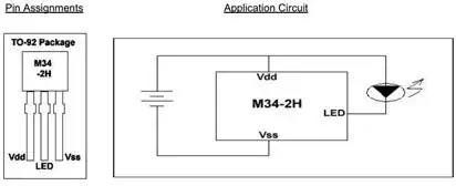
This part offers 2 Hz at 1/8 duty cycle. Other parts in the series:

  • M34-1L or M34-1H or M2581 : 1 Hz , 1/8 duty cycle
  • M34-2L or M34-2H : 2 Hz , 1/8 duty cycle
  • M34-4L or M34-4H : 4 Hz , 1/8 duty cycle
  • M34-8L or M2585 : 8 Hz , 1/2 duty cycle

The H parts drive 25 mA, while the L parts are for 16 mA.


Alternatively, for programming of the flashing pattern, and even higher efficiency, the NXP PCA9901 is an option: Quiescent current < 0.75 μA!

This 8-pin TSSOP part can be "trained" with a sequence of up to 3 blinking elements, and will then continue to blink as trained. The programming connection can be removed after training, and this programming is achieved via a single signal line from any standard microcontroller, using the 1-Wire protocol.

PCA9901

The single resistor in the schematic sets the LED drive current, between 1 mA and 20 mA. It itself does not carry significant current (less than 1 μA), so will not drain the battery noticeably.


Given the choice, the NXP part would be a recommendation, both because it is from a major manufacturer, and because the blink pattern can be optimized down to 1/1024 duty cycle if needed, and cycle time varied across a wide range, covering the OP's entire blink-rate range of interest. Lower the duty cycle, longer the battery will last.


Update:

Adding another simple, highly efficient flasher IC to the mix:
NTE876 LED flasher / oscillator operates from 1.15 to 6 Volts, delivers up to 2 Volts to the connected LED at up to 45 mA, and needs an operating current of merely 0.75 mA maximum.

This is an 8-pin DIP IC, though SMD equivalents are available too. It just needs one external capacitor for timing adjustment, the R of the RC oscillator is internal. The 45 mA LED drive current brings this closer to the current goal stated in the question.

Anindo Ghosh
  • 50,188
  • 8
  • 103
  • 200
6

This might not meet your application's needs directly, but if you want some ideas for really low-power LED flashing, take a look at the datasheet (the internal circuit, in particular) for the now-obsolete LM3909 LED flasher IC from National Semiconductor. This chip was capable of flashing a red LED for years on a single alkaline D cell.

Keep in mind that your ultimate battery life will depend primarily on the current you put through the LED, and what the duty cycle (on time vs. off time) is. In your question, you've specified some rather high duty cycles, so you shouldn't expect much lifespan, especially from coin cells.

The LM3909 succeeded because it used a very low duty cycle, and very little of its overall operating current was wasted on things other than lighting the LED. Even most of the charge that went into the timing capacitor on each cycle got dumped through the LED to help light it (it also helped to boost the voltage, so that a 1.5V battery could light a 2V LED).

Dave Tweed
  • 168,369
  • 17
  • 228
  • 393
3

LED Flasher circuit

These schematics run on 3V, I tested it myself with BC547 and BC557 as NPN, PNP, respectively.

This does not require programming microcontrollers, ICs, it's just two transistor + some RC components. I bet you can get this in one cm^3!

By changing the RC values (play a bit with that, with a normal LED connected) you can adapt the frequency and duty cycle.

However, I have to warn you: CR2032 isn't the best battery you can get and IR is warm, so it uses some current. Let's say you blink the LED 20 times a sec and 20ms long. That makes it on for 40% of the time, giving you a resulting current of 40mA, quite a lot.

You can also use the LM3909, as Dave Tweed already mentioned.

  • 4
    -1 for low-efficiency design. What's that 22 \$\Omega\$ resistor doing but making heat? At 100 mA you are burning almost 1/4 W there whenever the LED is on. That's more power than the LED! The blinking circuitry certainly draws some current, too. – Phil Frost Jan 07 '13 at 12:33
  • 1
    True, trying removing the resistor is a good idea! Didn't make the circuit myself so I cannot change it. –  Jan 07 '13 at 12:35
  • If you remove the resistor, there won't be any current limiting. With ideal components, this means the universe explodes. With real components, this probably means you use the internal resistance of the battery instead. That, and the LED won't blink anymore. – Phil Frost Jan 07 '13 at 12:47
  • Okay, but that means the resistor has to be there, so what's your problem? –  Jan 07 '13 at 12:48
  • No, it doesn't have to be there. Look at my answer. No current limiting resistor there. Alternately, you could design it so the LED gets shorted to the battery, and let the battery's internal resistance (which is unavoidable) do the limiting. Olin's answer takes that approach. – Phil Frost Jan 07 '13 at 12:59
  • Yes, but that isn't simple anymore, with a micro. Well, we'll see what the questioner thinks. –  Jan 07 '13 at 13:00
  • so will this circuit work or not? I'm unfortunately not in a position to make an educated guess. – memyself Jan 08 '13 at 12:07
  • 1
    @memyself Not very efficient, battery will not last long with this design. – ExcitingProjects Jan 08 '13 at 12:59
2

This is probably the simplest circuit:

Only 4 parts, and that includes the LED and the battery. (By the way, the only reason the battery looks so strange with 5 connections is because that's how the CR2032 battery holder I happen to have in my library works. The three negative connections are actually just solder bumps on the board.)

This is not a circuit I recommend for a industrial application where robustness is important. It plays fast and loose with some specs, but you asked for "simple". This sort of shortcut can be quite appropriate for a disposable consumer item, at toy, etc.

Note that there is no resistor in series with the LED. This is generally a bad idea, but as I said, this is a shortcut in favor of simplicity. A CR2032 battery has such high internal resistance that the current will be limited to what the micro and LED can handle in reality. The fact that the LED is a diode and its current goes down quickly at some voltage will help keep the voltage from collapsing to the point where the micro won't work, especially if the pulses are kept short.

For a better circuit, put a resistor in series with the LED. You can keep going and even put a small inductor in series followed by capacitor to ground to provide a short term local energy reservoir to run the LED off of during the pulses. This is then recharged more slowly during the off time. Going further, you can add a transistor that allows for more current than the PIC output can sink. There are lots of tradeoffs possible here to favor robustness and less battery abuse at the expense of more parts and less simplicity.

The PIC 10F200 is about as simply as you can get to make a digital oscillator. It's small, cheap, takes little power, you can have any kind of blink pattern you want, and timing will be accurate to a few percent. This is certainly better than a 666 timer.

If the point of this is to be a IR beacon, then you only need very short pulses with a low duty cycle. It's better to spend the energy on a short and bright pulse than a longer and dimmer one. The brighter pulse will have better range. For beaconing, you need to modulate the signal anyway due to the potentially high ambient level.

Olin Lathrop
  • 310,974
  • 36
  • 428
  • 915
  • is there an alternative PIC that I could use? I don't seem to be able to find the 10F200. Would any 12FXXX or 16FXXX or 18FXXX do, or do I need a special one? – memyself Jan 07 '13 at 15:40
  • I assume it's easy to use a 8pin F200? http://ww1.microchip.com/downloads/en/DeviceDoc/41239D.pdf I guess it's a matter of connecting the GP0 to GO3 PINs accordingly? – memyself Jan 07 '13 at 15:53
  • @memyself: There at lots of PICs that can do this, but the 10F200 is the smallest and cheapest of them all. They are definitely readily available out there. I would start at microchipdirect, but surely many others carry it too. This is not a obscure part. – Olin Lathrop Jan 07 '13 at 17:34
  • No it will not. From the datasheet linked before: max 25mA current on any I/O pin, sunk/sourced. See section 12.0: electrical characteristics. –  Jan 08 '13 at 08:18
  • Haha, I sometimes need a [sarcasm sign](https://www.youtube.com/watch?v=DF7MroTLDfU) :-) –  Jan 08 '13 at 09:05
  • will this circuit work? the suggested solution seems to have gotten down-voted. – memyself Jan 08 '13 at 12:08
  • @AnindoGhosh so what are the ramifications? Sorry, but unfortunately I can't follow all arguments here :( – memyself Jan 08 '13 at 12:16
  • 1
    @memyself This circuit will not be able to supply (sink) the 100 mA that you have specified for your LED. It will run the LED at 25 mA or thereabouts. If that is sufficient, there are simpler solutions available which do not even need a capacitor. Would you like a couple of such options? – Anindo Ghosh Jan 08 '13 at 12:21
  • 2
    As I said, the circuit as shown plays fast and loose with some specs in favor of simplicity, as the OP asked for. 100 mA is absurd from a coin cell anyway, so it's pointless to worry about that. You can tie the three output pins of the PIC in parallel. I would have shown that if I had thought about it at the time. That would definitely make the CR2032 coin cell the limiting factor for LED current. – Olin Lathrop Jan 08 '13 at 13:27
  • @AnindoGhosh I don't think 25mA will make the LED light up. So I guess that's not an option. I could run the LED with the CR2032 for 4 hours so far and I really just want to extend the battery life to 8 hours or maybe 12 if possible. Hence the blinking. – memyself Jan 08 '13 at 15:44
  • @OlinLathrop please feel free to submit another solution! – memyself Jan 08 '13 at 15:44
  • @AnindoGhosh You'll find a link to the spec sheet in the first sentence of my question. Hope that helps! – memyself Jan 08 '13 at 16:07
  • @memyself According to the Radiant Intensity graph of the Characteristic Curves in the datasheet, the LED lights up fine at 10 mA. – Anindo Ghosh Jan 08 '13 at 16:12
  • @AnindoGhosh could you explain to me what figure you mean and how you see that it needs 10mA only? The lowest value I found in the spec sheets was 20mA. Many thanks! – memyself Jan 08 '13 at 16:34
  • @memyself Page 7 of datasheet, second image on left. This discussion has extended beyond what comments are meant for. The EE chat might be a better place to continue this. – Anindo Ghosh Jan 08 '13 at 16:46
1

For this kind of battery powered application, you can use TI's MSP430 micro-controllers. They come in very small packages and consume very low power because of its various sleep modes. In software you can determine the blink rate / duty cycle to conserve energy. Because it will be software controlled, you are not stuck to one IC device.

To drive the LED use a MOSFET with low internal resistance. You can use a commonly available 2N7000 or BS170 for higher current rating. These transistors are available in SOT23 package therefore reducing the size of the physical design.

Edit: Here is all you need to blink an LED using an MSP430. You can start your rapid prototyping using the launchpad and once your design is perfect, implement a standalone MSP430 based design. With launchpad acquaintance, you may gain other helpful micro-controller / programming skills.

Chetan Bhargava
  • 4,612
  • 5
  • 27
  • 40