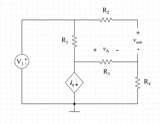
Redraw Schematic
At your stage in the game, I recommend that you redraw every schematic. In fact, you should redraw a schematic over and over until it "looks better" to you. There are some general helpful rules (I'll mention them, shortly, in the Appendix below.) But they are only a guide. An issue is that you need to develop a sense about things and, over time, to also acquire some standard thinking tools that allow you to more rapidly work out how better to redraw a schematic. Practice plays a huge role in developing those tools. So do not shy away from redrawing schematics. It should become second nature to you.
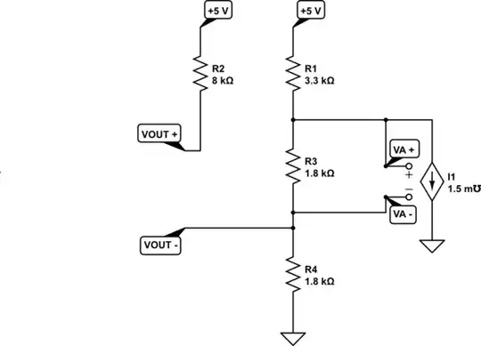
For example, here's what my mental tools suggested I should draw:
simulate this circuit – Schematic created using CircuitLab
(Note: In the above schematic, \$V_\text{A}^-=V_\text{OUT}^-\$.)
The above schematic draws your attention to a simple three-resistor divider from the \$+5\:\text{V}\$ rail towards the ground reference. It then adds the current sink, controlled by a voltage, on the right side. On the left side, you can then see the final addition -- the output voltage arrangement.
These things may help you in attempting to correctly write your equations. For example, it is very easy to observe that without the current sink your problem would be quite trivial. But that with its complicating addition, it's really fairly simple as it only draws current out of one node, sinking it to ground. Yes, doing so alters that node's voltage and also the voltage across \$R_3\$, but this clearly isn't rocket science, either.
It's also crystal clear (or should be) that you only need two equations in two unknowns to get started. You will, of course, need a separate approach to produce a Thevenin resistance as seen from the \$V_\text{OUT}\$ pin-pairs. But actually that's just the same two equations but with the addition of one change before solving again. So it's not that bad, really.
Does this help in any way?
Nodal Analysis (KCL)
You wrote:
This is a self-learning thing I've been doing over the summer
So I'll try to walk you through the pair of KCL equations that, when solved simultaneously, should provide a starting point for achieving (a) and (b). I'll also add another thought about how to achieve (c).
All of the currents flowing out of a node (left side of the equations below) must equal the currents flowing into a node (right side of the equations below.) Although the method I use for setting up the equations correctly isn't often taught, it is how one of the steps of Spice handles things and I find using the idea helps me avoid uncaught errors when on automatic pilot. In short, it just flows out, easily. Follow along and see if you understand what I did.
So here it is:
$$\begin{align*}
\frac{V_{\text{A}}^+}{R_1} + \frac{V_{\text{A}}^+}{R_3} + I_1 &= \frac{5\:\text{V}}{R_1} + \frac{V_{\text{A}}^-}{R_3}\\\\
\frac{V_{\text{A}}^-}{R_3} + \frac{V_{\text{A}}^-}{R_4} &= \frac{V_{\text{A}}^+}{R_3} + \frac{0\:\text{V}}{R_4}
\end{align*}$$
Now, you separately know that \$I_1=1.5\:\frac{\text{mA}}{\text{V}}\cdot \left( V_{\text{A}}^+ - V_{\text{A}}^- \right)\$. So the final arrangement is:
$$\begin{align*}
\frac{V_{\text{A}}^+}{R_1} + \frac{V_{\text{A}}^+}{R_3} + 1.5\:\frac{\text{mA}}{\text{V}}\cdot \left( V_{\text{A}}^+ - V_{\text{A}}^- \right) &= \frac{5\:\text{V}}{R_1} + \frac{V_{\text{A}}^-}{R_3}\\\\
\frac{V_{\text{A}}^-}{R_3} + \frac{V_{\text{A}}^-}{R_4} &= \frac{V_{\text{A}}^+}{R_3} + \frac{0\:\text{V}}{R_4}
\end{align*}$$
If you solve those, you'll have both \$V_{\text{A}}^+\$ and \$V_{\text{A}}^-\$. That will answer (a), directly. Separately, since you know \$V_\text{A}^-=V_\text{OUT}^-\$ and, without any current in \$R_2\$, also know that \$V_\text{OUT}^+=5\:\text{V}\$ then you have an answer for (b), too.
To answer (c), all you need to do is short out the \$V_\text{OUT}\$ terminals and find out what current flows in \$R_2\$. If you divide the open-circuit voltage for \$V_\text{OUT}\$ (determined already in (b) above) by the short-circuit current (which is the same as the current in \$R_2\$ as \$R_2\$ is directly in series with the short-circuit, itself), you'll have your resistance in hand, as well. To implement this idea for (c), you will need to modify the above equations to reflect \$R_2\$'s presence and then solve them again. From the newly computed \$V_{\text{A}}^-\$, you can get the current in \$R_2\$.
Keep in mind that you need to modify one of the above two equations in order to incorporate \$R_2\$ and compute the information needed to find the short-circuit current. Suppose \$V_\text{CC}=5\:\text{V}\$, the open-circuit equations solve for \$^\text{OC}V_{\text{A}}^-\$ and \$^\text{OC}V_{\text{A}}^+\$, and the closed-circuit equations solve for \$^\text{SC}V_{\text{A}}^-\$ and \$^\text{SC}V_{\text{A}}^+\$. Then the Thevenin resistance will be:
$$R_\text{TH}=R_2\cdot \frac{V_\text{CC}-\:^\text{OC}V_{\text{A}}^-}{V_\text{CC}-\:^\text{SC}V_{\text{A}}^-}$$
Appendix
One of the better ways to try and understand a circuit that at first
appears to be confusing is to redraw it. There are some rules you can
follow that will help get a leg-up on learning that process. But there
are also some added personal skills that gradually develop over time,
too.
As mentioned at the outset above,
I first learned these rules in 1980, taking a Tektronix class that was
offered only to its employees. This class was meant to teach
electronics drafting to people who were not electronics engineers, but
instead would be trained sufficiently to help draft schematics for
their manuals.
The nice thing about the rules is that you don't have to be an expert
to follow them. And that if you follow them, even blindly almost, that
the resulting schematics really are easier to figure out.
The rules are:
- Arrange the schematic so that conventional current appears to flow from the top towards the bottom of the schematic sheet. I like to
imagine this as a kind of curtain (if you prefer a more static
concept) or waterfall (if you prefer a more dynamic concept) of
charges moving from the top edge down to the bottom edge. This is a
kind of flow of energy that doesn't do any useful work by itself, but
provides the environment for useful work to get done.
- Arrange the schematic so that signals of interest flow from the left side of the schematic to the right side. Inputs will then
generally be on the left, outputs generally will be on the right.
- Do not "bus" power around. In short, if a lead of a component goes to ground or some other voltage rail, do not use a wire to connect it
to other component leads that also go to the same rail/ground.
Instead, simply show a node name like "Vcc" and stop. Busing power
around on a schematic is almost guaranteed to make the schematic less
understandable, not more. (There are times when professionals need to
communicate something unique about a voltage rail bus to other
professionals. So there are exceptions at times to this rule. But when
trying to understand a confusing schematic, the situation isn't that
one and such an argument "by professionals, to professionals" still
fails here. So just don't do it.) This one takes a moment to grasp
fully. There is a strong tendency to want to show all of the wires
that are involved in soldering up a circuit. Resist that tendency. The
idea here is that wires needed to make a circuit can be distracting.
And while they may be needed to make the circuit work, they do NOT
help you understand the circuit. In fact, they do the exact opposite.
So remove such wires and just show connections to the rails and stop.
- Try to organize the schematic around cohesion. It is almost always possible to "tease apart" a schematic so that there are
knots of components that are tightly connected, each to another, separated then by only a few wires going to other knots. If you
can find these, emphasize them by isolating the knots and focusing
on drawing each one in some meaningful way, first. Don't even think
about the whole schematic. Just focus on getting each cohesive section
"looking right" by itself. Then add in the spare wiring or few
components separating these "natural divisions" in the schematic. This
will often tend to almost magically find distinct functions that are
easier to understand, which then "communicate" with each other via
relatively easier to understand connections between them.
The above rules aren't hard and fast. But if you struggle to follow them,
you'll find that it does help a lot.
I also tell a bit of a tale and provide some examples of successful drafting
of schematics here.