-7

As a follow-up of my previous too generic question

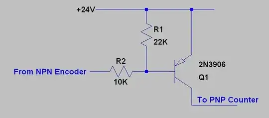
I have a signal generator (shaft encoder) that has 2 NPN outputs. I have a high speed counter that needs PNP signals. How can I convert the encoder signals, so the counter can use them. Both encoder and counter have a supply voltage of 24VDC. The counter can count up to 30 kHz, so speed is also important.

UPDATE: As was guessed in the comments, this is indeed for industrial machinery. An old bending machine's (iron pipes) logic is broken and is being replaced by something completely new. It's while trying to get everything connected again, that this problem showed up.

My dad is the one who has replaced the old 1970's circuits by a PLC, and reprogammed the entire thing. (He's a retired bending machine architect/engineer).

What he's bumping into is that one issue with the incompatibility between the encoder and the generator. Since electronics isn't his specialty I convinced him that the internet might help him with these issues.

I'm sorry if we are using 'incorrect terminology'. We are non-native english speakers, and technical terminology is even more difficult to get right.

I'll ask my dad if he can supply a schema, or some part info which might shed light on the matter

Toad
  • 235
  • 1
  • 3
  • 6
  • 3
    Please supply a circuit diagram of what you want to do. It is unclear what is meant by 'NPN output' and needs 'PNP signal'. I can guess, but I'm usually very bad at that. – jippie Dec 16 '12 at 18:52
  • I don't think you have been clear enough. With NPN outputs do you mean NPN open collector outputs? And what do you mean with PNP inputs? – Vladimir Cravero Dec 16 '12 at 18:52
  • 1
    A "PNP or NPN" interface is nebulous. Think again. There are 3 basic config's of BJT's; Common Emitter (CE), Common Base and Common Collector(CC), THEN 2 possible outputs for BJTs, C or E THEN 2 choices for logic switches, normally open (NO) or Normally Closed (NC). Although that being said encoders often using open collector interfaces with external active termination (usually Pull up ... don't assume) So please reword you question in standard engineering specifications like you would read an Logic gate spec; 0/1 threshold, hysteresis, voltage margin, input or output impedance (R &/or C) – Tony Stewart EE75 Dec 16 '12 at 19:16
  • Can you provide some scope to your project.. ie. application, purpose , then question. A Shaft encoder has 2 quadrature outputs for determining direction. Do you need to both directions? How long a cable? pf/ft? any EMI issues nearby? – Tony Stewart EE75 Dec 16 '12 at 19:21
  • Huh? What is a "NPN output"? What is a "PNP signal"? Don't make up your own names for things and then expect people to know what you're talking about. – Olin Lathrop Dec 16 '12 at 19:39
  • If you don't know how to specify the interface. then at least give a link to the products and intended purpose such as Tach only and interface distance, power avail.,etc. – Tony Stewart EE75 Dec 17 '12 at 00:25
  • 3
    @All Commenters... In the industrial sensor business it is common to see the terms NPN or PNP output. Each of these are an open collector output that can either sink current to GND or source current from V++ respectively. Also common is the terminology for an NPN input that represents an impedance to V++ that can be pulled to GND using a so called NPN output. Likewise a PNP input is one that represents an impedance to GND that can be pulled to V++ using a so called PNP output. This terminology has been around for many many years. – Michael Karas Dec 17 '12 at 07:27
  • This is strange because I've searched it and I did not find much informations on that. – Vladimir Cravero Dec 17 '12 at 08:13
  • @MichaelKaras your guess is just as good as ours. Although it makes sense now you mention it, it is not stated if we're talking industrial sensors. Different people have different specializations and things can have different meanings for them. A circuit diagram or datasheets would have cleared this up. – jippie Dec 17 '12 at 08:15
  • 2
    @jippie - Problem with your comment is that I am not guessing. These terms are also common in the companion field of PLC industrial type controllers. I posted my comment to set the record straight because some here think that the original poster is making up terminology when in fact they are speaking out of their own lack of information. There is no denying however data sheets can often help a lot. – Michael Karas Dec 17 '12 at 08:36
  • 2
    "NPN/PNP" is not that nebulous if you're familiar with industrial machinery. NPN outputs are open-collector outputs that sink current. PNP inputs are inputs which are pulled down internally and require a positive voltage applied to them to register as active. – akohlsmith Dec 17 '12 at 12:21

1 Answers1

3

There are off the shelf devices that you can obtain to convert your NPN outputs to the PNP type inputs required by the counter. It is unfortunate that you were unable to acquire instrumentation that had compatible outputs and inputs. None the less it is possible to build your own simple circuit to do the conversion. The following circuit could be used as a guide to convert each signal line from NPN to PNP for the counter.

enter image description here

You may have to diddle with the values of the resistors some to ensure that the current being sinked by the NPN output of the encoder is within specification of the device while at the same time ensuring that the resistors are not too large that the stray capacitance in the circuit limits the bandwidth.

Michael Karas
  • 56,889
  • 3
  • 70
  • 138