0

I am designing a system to measure voltages from bio-potential sources and feed them into an ADC after filtering and amplification. The source has the following charactristics:

  1. amplitudes are in 10's of uV
  2. frequency band of interest is 3Hz to 50Hz. 3.The 2 differential inputs from the bio source would have a DC offset (sometimes as high as 900mV)

As it happens, the vast majority of other designs filter, amplify and then feed the signal into a MUX, which in turn connects different signals to the ADC to be read, something like this if we had 2 sources:

schematic

simulate this circuit – Schematic created using CircuitLab

The first thing that went through my mind, was that depending on the application, the op amps used in filtering stages will be expensive.

Is there something fundamentally wrong connecting the sources to the MUX and then feed them into the filtering circuitry? like this:

schematic

simulate this circuit

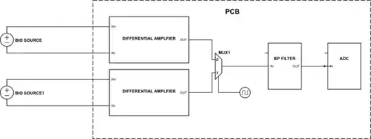
Highest frerquency of interest is 50Hz, am i wrong in assumming that the response time (transient response) of even an oridnary filter would be more than sufficient for such a low frequency?

NeuroEng
  • 462
  • 2
  • 13
  • 2
    Why do you think that the BP filter op-amps will be expensive? – Andy aka Jul 29 '20 at 13:02
  • What is the BP frequency? If the switching has (a strong) influence on the filtered signal depends on the ratio between the filter corner frequency and switching frequency. – Botnic Jul 29 '20 at 13:06
  • @Andyaka the 2 measured sources usually have a DC offset, sometimes as high as 900mV. This puts a limit on the supply, and if the gain cannot be that high, noise becomes a factor. most of low noise and high CMRR op amps i've seen are expensive – NeuroEng Jul 29 '20 at 13:08
  • @Botnic BP would have a 3-50 Hz band. switching frequency will also be at about 500KHz. – NeuroEng Jul 29 '20 at 13:09
  • 3
    Does this answer your question? [Am I over-complicating this data acquisition design?](https://electronics.stackexchange.com/questions/279914/am-i-over-complicating-this-data-acquisition-design) – Dave Tweed Jul 29 '20 at 13:23
  • What is the range of amplitudes of the biopotential signals? Please edit the question to include this information. – The Photon Jul 29 '20 at 13:24

3 Answers3

1

Analog Mulitplexors, such as MC4051 available from several fab houses, will do just fine. There are quad 2:1, dual 4:1, etc in 14/16 pin packages.

The random thermal noise in a 100 Hertz bandwidth, with 1,000 ohm channel resistance, will be 4nanoVolt * sqrt(100 H) = 40 nanoVolts.

Any 1/F noise may be higher, since these muxes are not designed to minimize that crystal_defect behavior.

By operating at +- 5 volts (that is, use a -5v on the VEE? and +5volt on the VDD?), your switch will easily handle 0.9 volts of DC.

You need to use a Ground plane, and have substantial R+C filtering on the several power rails. You also need R+C filtering on the Channel Select inputs, to exclude MCU trash ( 0.5 volt or so, from internal switching as the program continues to execute).

To protect against ESD, EMI, RFI, I would insert a low_pass_filter in each input from your sensors: 1Kohm resistor and 0.1uF capacitor (non-polarized ceramic, using the GROUND plane (you are using one, right) as the Return side of the energy_shunting 0.1uF.

For confidence, you might examine the instruction manual (repair manual) of commercial equipment, and learn how they protect the inputs.

analogsystemsrf
  • 33,703
  • 2
  • 18
  • 46
  • Good suggestion to reading (old) repair/instruction manuals, for the schematics in them. Great source of information. My other favourite is patents, but they are very wordy and tend to design the universe. – P2000 Jul 31 '20 at 17:30
0

There should not be anything wrong other than you may require different filters for the different sources. If this is not the case then doing the filtering at the end of the chain is not uncommon. Actually it may be even best done by digital filtering after your ADC. However if 50Hz is your highest frequency what is the lowest, DC ? It may however depend on other things such as your resolution required 8, 10 or 16 bit ? If you're considering purely low frequency audio and no DC, there are audio codecs with built-in digital filters that may be adjusted as required, even according to your selected source requirements ...

citizen
  • 2,241
  • 7
  • 16
  • The lowest frequency would be 3 Hz, and since the maximum frequency is 50Hz, 100Hz is minimum required (Nyquist theorem) but I am going to use a 500KHz sampling/switching frequency for the multiplexer. So if as you said it could even be beneficial, can you put the differential amplifier after the MUX as well? – NeuroEng Jul 29 '20 at 13:13
  • Hi, well this depends on the signal to noise on the source side. You mention the frequency range, but amplitude levels don't seem to be an issue... Are these 1V, 10V or mV sources ? If they are very small signals then best to amplify them first to keep the noise down as early as possible in your signal chain. Otherwise if high levels, and no other interference possibly affecting the sources, then I guess having the differntial amp after the MUX is OK. You need to figure out the requirement for your dynamic range and then work out if gain is needed or not etc... – citizen Jul 29 '20 at 13:54
  • 1
    Mind you the Mux is not differntial unless you find one that does this etc... so keep that in mind to that you may need differntial to single-ended conversion first ... – citizen Jul 29 '20 at 13:55
  • Yeah I already have thought about it, since all the sources are measured against the same reference, the differential inputs after MUX would be the signal coupled through the MUX and the reference, but I do understand your point. I have edited the question to include peak voltages as well. Thank you for your time and input. – NeuroEng Jul 29 '20 at 13:57
  • Well that's differnt then. You say up to 100uV absolute peak then best to keep all gain stages and the source. Is the common-mode DC important or can it be removed ? Work out what part of the signal is rquired, and if both, then yes its gonna be expensive because of the 900mV common mode and the uV small signals etc... as you guessed ... It may just be cost required to bear to get the thing working as you want, and to the specs you have been imposed ... – citizen Jul 29 '20 at 14:07
0

The main problem is that if your switching frequency is 500kHz, and the bandpass filter limits the signal to a maximum of 50Hz, then it will completely trash both signals. You will get a bandpass filtered version of what you get if you mix the two signals together.

The signal seen on the input of the bandpass filter will be rapidly switching back and forth between the two inputs. Imagine at some moment, for a few milliseconds, signal 2 is +10uV and signal 1 is -10uV. The bandpass filter will see a 500kHz signal of amplitude 20uV peak-to-peak. Since 500kHz is way outside its 50Hz range, it will remove that signal, and you'll get 0uV out.

Simon B
  • 18,609
  • 1
  • 29
  • 55