I have found this circuit which is supposed to be a current-limiting circuit:

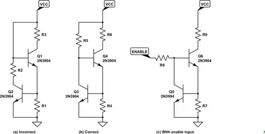
simulate this circuit – Schematic created using CircuitLab
'R1 is used as a current's resistor. It monitors the current flowing through Q1. The voltage drop across R1 increases as the current through Q1 increases. If the voltage at the top of R1 reaches 0.65V Q2 begins to turn on. Q2 diverts some of the current from the base of Q1 and sends it to ground. This reduces Q1's collector current'.
However, I am having trouble understanding this:
When Q2 is on the voltage drop of R1 will become less and Q2 must be off despite we say it is on and this will create a closed loop of paradoxes.
Where am I wrong?

