-4

I see a lot of text on the internet and here telling us how to de-bounce a switch, in my case a push button. But I have tried all these circuits and I find that nothing other than a 555 monostable worked for me so far.

This is why I ask that you only answer if your knowledge is practical, not textbook, not hear-say, only if you have done it either recently or often enough that you have experienced the difference between theory and practice!

I have tried RC with inverter and that doesn't work except with Schmitt-trigger inverter (and I guess then Schmitt trigger buffer too), but even that not 100% reliably (I would say one extra triggering in about 100.)

My test setup is without a storage scope, just a 74LS161 counter and 4 LEDs hooked up.

My preferred solution is an S-R-latch, with 2 NAND gates (74LS00), but I had no luck whatsoever with that, regardless whether I tied the switch to high or to ground.

One thing nobody seems to mention is the darned make-before-break variety of push-button switches. Those are a total non-starter. But now that I just came home with 2 more buttons, tested and found them to be break-before-make, hooked them up to my DYI S-R-latch and I still get salves of up to more than 16 counts! Rarely, but I can't count a set of 16 without at least one double trigger.

Why am I the only one who has such bad luck? I show you my breadboard photos if you don't believe me. I put it on YouTube.

This is why I don't trust any theoretical answers, I built every circuit in the book(s) and can testify for several of them they totally and utterly fail right out the barn. I think most people who write about this don't actually have the experience.

So far RC with Schmitt-trigger is the only thing I could get working at 99% reliability, but not better, and I don't want the monostable, I really want the S-R latch (push - S, release - R).

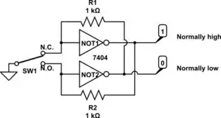
UPDATE: people want to see schematics, so here is what I am now targeting. I have built all other circuits I could find. I will try the RC again from one of the answers. But for the SR-latch it's this:

schematic

simulate this circuit – Schematic created using CircuitLab

I have three different types of double throw buttons, all I can get my my hands on, and one is MBB, doesn't work, the other is one of those with a little lever, like a morse code switch, supposedly extra precise, but nope, it bounces back and forth. The other is a button like the first but BBM -- at least most of the time.

I find that the double throw buttons are all bad. The third one is the best, but still it has horrible bouncing around, because when I hold it just right it can even do a MBB action. So, that may be the problem I am having. I just can't get a decent switch.

This means, for me the SR-latch trick is out, a no-go.

I need to use a single throw button then and try again with RC. I will work off the other answer below and report back.

UPDATE: I see a lot of negative ratings, but I don't care! I am here representing the experimental truth of the matter and not text book. Yes, we are on breadboards but these things do not work.

It probably has to do with the fact that the double throw buttons are all bad, at least in micro-switch format, they bounce around like crazy, make-before-break and apparently also bouncing between the two sides. The only circuit that I can use to do an push-release action with <10% glitch rate is the one I have described here:

Is it possible to use just a capacitor to debounce a button?

Gunther Schadow
  • 1,441
  • 7
  • 22
  • 2
    You do not say what kind of button it is. Most buttons are SPST. But then you start talking about make-before-break which doesn't make sense for a SPST button. Also, you do not make it clear whether you want momentary or latching behaviour. Also, post your schematics. – DKNguyen Jul 08 '20 at 23:03
  • 1
    If you know the debouncing literature, the S-R-latch is a standard -- and often praised as the best -- solution, and it depends on a double throw button. But I take anything at this point. I want to see someone saying: "dude, I have done the SR latch debouncing 100s of times and it always works, you must be doing something wrong!" – Gunther Schadow Jul 08 '20 at 23:07
  • 7
    Show one circuit schematic and code that doesn't work and we can try to fix it. – Transistor Jul 08 '20 at 23:14
  • 4
    If you can't make an S-R latch work with a break-before-make SPDT switch, you're doing something totally wrong! It could be your wiring technique, poor power supply decoupling, or a host of other things. You need to show us more details (schematics, photographs) about your attempts. – Dave Tweed Jul 08 '20 at 23:33
  • Are you working on a breadboard? Do you have bypass caps? Are you using all LS TTL chips, no other types? Dude, I've never done hardware debouncing with SR latch, but I still think you must be doing something wrong. – Justme Jul 08 '20 at 23:35
  • I use digital filters for both digital and analog inputs. Switch inputs must have same state 4 samples in a row for the change to be passed to a bit that actually represents the state of the button or switch. Samples are 10 mS apart so switch bounce is filtered out. –  Jul 08 '20 at 23:41
  • If you can use a DPST switch, then why are S-R latches not working for you? It DOES WORK if the board layout is clean and proper. Else ground bounce can ruin any design. –  Jul 08 '20 at 23:45
  • "dude, I have done the SR latch debouncing 100s of times and it always works, you must be doing something wrong!" The contact bounces off the target throw to float but never back to the previous throw. So a storage cap to prevent drift voltage after the 1st contact. dV/dt=Ic/C bounce tme may be 5ms small to 20 ms big switch for a SPDT and less for a mini button momentary switch which could be used to toggle instead of S/R. Vcc ought to be >100x bigger than the debounce cap. e.g. 0.1uF on IC and <1nF on switch contact to ground. This prevents Vcc surges. – Tony Stewart EE75 Jul 09 '20 at 00:03
  • 1
    Please post schematic diagrams of what you have tried. In particular, post the schematic of the R-S version. Even better, add a photo of your breadboard. – Dwayne Reid Jul 09 '20 at 00:06
  • 1
    `Why am I the only one who has such bad luck?` .... it has nothing to do with luck – jsotola Jul 09 '20 at 00:09
  • The chips being LS TTL type, the resistance value being correct is quite important. What pull-up values you use? The value will also be radically different if they are pull-ups or pull-downs. Pull-downs on LS chip are almost never used because it would require very low resistance. And since it is 74LS00, the correct way is to have pull-up resistors, and switch will ground inputs. – Justme Jul 09 '20 at 00:31
  • @GuntherSchadow It's a tough question. Different switches have different bouncing characteristics. And, stuck with an analog solution, you must tailor your circuit to the exact specifics of the switch behavior. Even then, there's little guarantee as switch behavior doesn't nest well within a tight Gaussian curve. It's spread out, may be multi-modal, and hard. I've spent many, many hours on this and the best results -- those that are most robust yet providing the best "feel" for an operator require both analog and also digital processing. In those cases, I've had the best consumer results. – jonk Jul 09 '20 at 04:20
  • @GuntherSchadow That said, I've also found that without analog processing I can use digital processing approaches within an MCU to produce consistently "pretty good" results. This means quick responses (a responsiveness on the order of 20 ms, say, which most people consider "very good" and "snappy" enough for gaming needs) as well as consistency. There's a specific state machine I use for this. I've written about it [here](https://electronics.stackexchange.com/a/269938/38098), before. With an 8-bit MCU, you can simultaneously process 8 switches at a time. Decent when things are set up well. – jonk Jul 09 '20 at 04:29
  • this may help ... https://youtu.be/kRlSFm519Bo – jsotola Jul 10 '20 at 19:31

4 Answers4

3

Your problem is not knowing input impedance chances with bias voltage on TTL.

TTL floats to a logic "1" input with Iin =0 uA at 2x Vbe drops or ~1.3V . This is unlike CMOS.

  • The impedance is infinite when floating at this voltage. But at 0.4V the input impedance is 1K due the common base input bias current.
  • To ensure the TTL has a safe margin or a valid "1" input > 2V the input impedance is > 100K with 20uA max at 2.7V.
  • So to make it work, I biased the input towards the tipping point of input current between 1 and 0 so that the target voltage is lowered and transition time is extended during switch bounce.
  • this is somewhat nonlinear Ohm's Law so I won't explain beyond this for now.
  • Naturally, a Schmitt Trigger works better but still not good enough unless you use a much larger Cap.

For a 10ms bounce time and T=RC= 10ms so C=10ms/3.3k = 3uF

schematic

simulate this circuit – Schematic created using CircuitLab

This is one way to do it with short twisted pair wires.

Decoupling cap MUST be near IC and much larger to absorb the transient.

some Hypothetical causes for failure.

  • Using TTL instead of CMOS. (requires a different solution.)
  • Not using a decoupling cap
  • excessive long sig/ground wires.
  • Must be Break Before Make (common type) switch.

It is much preferred to use 2 momentary switches to gnd or toggle 1 switch using TTL due to the large input current.

So learn to use CMOS instead. Input Impedance is > 10M but beware of ESD even if protected.

Tony Stewart EE75
  • 1
  • 3
  • 54
  • 182
2

This always works.

The two push buttons can be replaced by a SPDT switch.

schematic

simulate this circuit – Schematic created using CircuitLab

Here is a simulation

Dave Tweed
  • 168,369
  • 17
  • 228
  • 393
jsotola
  • 2,497
  • 2
  • 12
  • 21
  • I also think it always work, if built properly. If built on a breadboard, without bypass caps, etc, operation might not be guaranteed. – Justme Jul 09 '20 at 00:59
  • As soon as you add a double throw switch the problem starts. And that is the intention here. I think with the 2 separate buttons it would indeed always work. – Gunther Schadow Jul 09 '20 at 18:12
  • @Gunther: Once again, please edit your question to show the circuit that doesn't work. – Transistor Jul 09 '20 at 19:17
  • @Transistor, I did, one hour before you asked. – Gunther Schadow Jul 09 '20 at 22:49
  • 1
    @GuntherSchadow remove D1 and D2 .... increase R2 to 1 k ohm – jsotola Jul 10 '20 at 01:34
  • @jsotola -- I didn't want to believe it first, but taking out the D1 and D2 does help indeed. Thanks. There is still a huge problem with one of the switches, but the other one is working fairly consistent now. And yes, it was 1 k ohm all along. – Gunther Schadow Jul 10 '20 at 19:07
  • 1
    even though D1 and D2 produce light, they are still diodes, so view them as such ... a regular diode would pull the high output down to ~ 0.7 V ... an LED would not pull down the output as much, but it would still pull the output down ... a series resistor with the LED may help ... the simplest solution would be to use one of the unused gates as a buffer to drive the LED – jsotola Jul 10 '20 at 19:17
1

You have no series resistors on your LEDs, which is naughty and eats up noise margin, especially if the LEDs are red color.

You do not show any bypass capacitors. You NEED a bypass capacitor quite near each chip, 100nF ceramic is a good value.

Quite likely your problems will go away when you fix those things.

Spehro Pefhany
  • 376,485
  • 21
  • 320
  • 842
  • Oh come on! I have bypass caps yes, and it doesn't make a difference. Nor do series resistors, they aren't needed here. I can run these chips with a 2 MHz clock on breadboard without a problem. When you say "quite likely" I really doubt you actually dealt with these problems for real. The quality of switches is really bad, that's the primary problem for all I can see. – Gunther Schadow Jul 09 '20 at 22:46
  • 1
    So your schematic is incomplete. Poor quality switches will not cause bouncing, it will cause failure to change state. I ran into debouncing in about '71 with RTL flat-pack circuits from Polypacks and tried the SPDT switch method, which, of course worked, but these days it's usually done with a couple lines of code in firmware. – Spehro Pefhany Jul 09 '20 at 22:52
  • "poor quality switches" most definitely cause bouncing. – Gunther Schadow Jul 10 '20 at 18:56
  • 2
    I apologize, there was clearly a problem with D1 and D2 – Gunther Schadow Jul 10 '20 at 21:35
  • No problem. It's better to have the outputs (especially on LSTTL) sinking current and use a series resistor like 1K. Reverses the logic, of course. – Spehro Pefhany Jul 10 '20 at 22:05
1

If you really have LEDs connected between logic signals and ground without current-limiting resistors, that's your problem! LSTTL does not have a lot of high-side drive to begin with, and the bare LED will completely overload it, killing your valid logic levels.

Basically, a red LED has a forward voltage drop somewhere in the vicinity of 1.7 V, and it will easily pull a high LSTTL output down to this level. However, the minimum VIH for a TTL input is 2.0 V — which means that you're operating with a negative noise margin. It's no wonder that the counter behaves in a flaky manner.

If you really want to monitor signal levels, buffer your LEDs with 'LS04 inverters, and connect the LED between the 'LS04 output and Vcc with a 330-ohm series resistor. The LED will light up when the 'LS04 input is high, as desired.

schematic

simulate this circuit – Schematic created using CircuitLab


And just to demonstrate that I do indeed have "real world experience" in this area, here are a couple of photographs of a project I did back in the mid-1970s when I was still in high school. It's a "breadboard helper" that includes (left to right):

  • A variable-speed 555 oscillator (note the metal can!)
  • 8 DIP switches to ground
  • 8 buffered digital monitors
  • 2 debounced pushbuttons

The PCB was hand-drawn with a Sharpie pen. The circuit for the debounced pushbuttons is very simple, and you can see that the switch construction is pretty much the cheapest possible. Always worked perfectly.

schematic

simulate this circuit

front view

rear view

Dave Tweed
  • 168,369
  • 17
  • 228
  • 393
  • 1
    Yes, definitely D1 and D2 have contributed to the problem. The outputs A,B,C,D don't matter but definitely D1 and D2 did hurt the test circuit. – Gunther Schadow Jul 10 '20 at 21:34