8

I'd like to work through some basic logic circuits with some youngsters and wanted to build them up from scratch (transistors), not logic gates if possible.

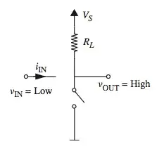
We've done the basics: buffer, NOT, AND, OR, NAND, XOR just using NPN mosfets and resistors. We've even been able to get to D-latches. As an example, the AND gates we're playing with have been build like this:

schematic

simulate this circuit – Schematic created using CircuitLab

The problem is that as the circuits have grown in complexity, with transistor emitters feeding into other transistor bases, I've only been able to get things to work by very carefully balancing resistor values to make sure transistors are triggered when they should be.

I would like to be able to build modular logic gates, which are identical and can just be plugged into one another without needing to carefully calculate resistor values.

Another restrictions is that we currently have 200 BC547ATA NPN transistors and a big bunch of resistors, so if its achievable without buying any more components, that would be ideal.

Dom
  • 191
  • 5
  • 2
    Why not use base resistors on a schematic like that? – uglyoldbob Jul 07 '20 at 13:56
  • 2
    Seeing how cheap transistors are, and how logic using a singular transistor type is virtually non-existent these days, I would suggest just getting some PNP transitors (or better nmos/pmos) devices so you can make a more complimentary series of circuits? – Joren Vaes Jul 07 '20 at 13:57
  • 1
    For larger systems you'll need an implementation with gain to restore noise margins and you'll probably want to drive actively high and low, not just on or off... so you'll need PNP types. Consider engineering education works in reverse onion layers of abstraction. You build a discrete gate then you use IC gates, then fixed function ICs with MCUs, CPLDs and FPGAs. People keeping it all low discrete aren't being very realistic about learning how anything useful works. – Chris Stratton Jul 07 '20 at 13:58
  • 2
    Suggestion: Only connect NPN transistors near the ground and PNP transistors near the power rail, and then you won't need to balance resistor values. Your example circuit has NPN transistors near the power rail which is bad. – user253751 Jul 07 '20 at 14:25
  • 5
    Actually, your "AND gate" shown above doesn't work. The LED will light up as soon as the lower switch is turned on, regardless of the state of the upper switch. Ah, never mind -- I just noticed you said "mosfets" even though you also said NPN and used BJT symbols in your schematic. Before you go any further, you should learn what the differences are between MOSFETs and BJTs. But if you are using N-channel MOSFETs, you'll need pull-down resistors on the gates. – Dave Tweed Jul 07 '20 at 14:31
  • Actually, the BC547 **is** a BJT, so my original comment stands -- the AND gate doesn't work. – Dave Tweed Jul 07 '20 at 14:38
  • @uglyoldbob I was working from memory when I drew the schematic but I must have had resistors on the bases. – Dom Jul 07 '20 at 14:56
  • @DaveTweed Schematic above is incorrect. I would have had resistors on the bases, which when you balance the values correctly allows it to function as an AND gate. – Dom Jul 07 '20 at 14:57
  • Seems to me that the fact you can’t really use the oversimplified circuits to make arbitrarily complex logic circuits is a useful lesson in itself. Why not use 74HC logic like everyone else? With luck they’ll learn about latch-up too. – Spehro Pefhany Jul 07 '20 at 15:01
  • @SpehroPefhany My aim is to lay a foundation and to transition to packaged logic gates as soon as possible. I just don't think it would be helpful for a nine year old to start from a 'black box', as at least a transistor can 'understood' as an electronic switch. – Dom Jul 07 '20 at 15:07
  • It still won't work properly with MOSFETs as the gate is floating when the switch is open -- the voltage on the gate will be indeterminate. It needs a pull-down R at each gate. – jp314 May 12 '21 at 04:57

5 Answers5

13

If all you have is NPNs and resistors, you'll want to use some form of RTL. Here, the basic logic element is the NOR gate. The one-transistor gate uses fewer transistors (obviously), but the multi-transistor gate is more robust in several ways.

And there's a teaching opportunity here, to show how the NOR gate is a "universal" logic element — all other functions can be created by combinations of NOR gates (including the degenerate 1-input NOR gate, or inverter).

Even large systems have been built this way. The original Cray-1's logic was entirely implemented using 4- and 5-input ECL NOR gates!


One implementation strategy would be to build up individual 3-, 4- or 5-input gates on single-inline modules like these:

uni-sip modules

(source)

These are easy to plug into a breadboard socket, allowing the students to focus on the logic they're building. If you need a large number of them, have a custom PCB made.

And if you're really ambitious, you could plug them into a universal wirewrap card for larger projects and a more permanent implenentation.

universal wirewrap prototype card

Dave Tweed
  • 168,369
  • 17
  • 228
  • 393
  • 2
    May also be worth looking at the [Hackaday.io TTLers group](https://hackaday.io/project/8449-hackaday-ttlers), which contains a variety of articles by people interested in discrete logicimplementations, including [in-depth discussions of the implementations of RTL as used by DEC](https://hackaday.io/project/8449-hackaday-ttlers/log/130460-bizarre-dtl-logic-levels-the-discrete-component-pdp-8) and other early computer manufacturers. – occipita Jul 07 '20 at 14:44
  • Dave - any suggested improvements for a basic as possible gate for use on your modules, compared to the DTL suggestions in my answer? – Russell McMahon Jul 08 '20 at 02:33
  • @RussellMcMahon: No, not really. I happen to have a reel full of logic-level N-channel MOSFETs left over from an old project, and I have been toying with the idea of using them to build a simple CPU, using the SIP concept described above -- three 3-input NOR gates on a 14-pin SIP, with an optional LED on each output for visualization. Two such modules (6 gates) would be enough to build an edge-triggered FF. I have a larger wirewrap card that has over 4000 connection points, which would hold over 280 such modules. 840 gates (2520 transistors) is more than enough for a simple CPU. – Dave Tweed Jul 08 '20 at 03:42
  • ... Dunno if it will ever happen, though -- lots of higher priority projects already in the pipeline. I think for now it's enough to know that I could. – Dave Tweed Jul 08 '20 at 03:42
4

Building discrete logic with MOSFETs is much easier than bipolar transistors, because the high gate impedance prevents the issue you describe. NMOS circuits are easier than CMOS (which is more commonly used because it has lower power).

occipita
  • 179
  • 6
  • Wouldn't MOSFETs be more sensitive to ESD? – Simon Richter Jul 08 '20 at 08:05
  • 1
    @SimonRichter: Discrete MOSFETS would be "more" sensitive to ESD than discrete bipolar junction transistors, but in an environment with reasonable humidity that doesn't have a unusually static-prone carpet, they should generally survive ordinary handling. Factories use ESD protection measures because even 0.001% fallout from static would be unacceptable, but in a lab situation transistors would more likely be destroyed by improper connections than by ESD. – supercat Jul 08 '20 at 15:33
3

I think you want to follow TTL logic. I haven't done it myself, but the problem with this simple wiring up of transistors that you are showing is prone to fail when you put more of them together.

So here is the TTL way of doing things. This is a NAND gate

TTL NAND gate

what I find a good instruction here -- and you might want to sprinkle in a littler diode-resistor logic too -- is that you are entering on the emitters. This keeps the students appreciating the difference between how the logic bits "flow" as opposed to how currents flow, you know, appreciating the fact that a logic 0 state means the output element needs to sink current (that's the same lesson with the diode AND gate).

And you don't need dual emitter transistors, I have read you can just wire two transistors in parallel, base and collector together and separate emitters.

PS: if you can use my approach (please report back) and you find that you're now in need of more transistors, I will donate another 200 to your project.

The totem-pole output stage will also be interesting to experiment with. The whole nine-yards: open collector, normal always on, and three-state. Cool project.

Gunther Schadow
  • 1,441
  • 7
  • 22
  • 1
    That's really generous, thank you. Its just my cousins kids at the moment, so we should have enough stuff. – Dom Jul 07 '20 at 16:30
  • A TTL circuit would have a transistor on the high side of the output, instead of just a resistor. – supercat Jul 08 '20 at 15:34
  • @supercat, you mean the "totem pole" output stage, right? But that's not what defined TTL. There are many open-collector TTL circuits available too. I used this picture from Wikipedia's TTL article since it was the simplest one and the key was to show the difference in input stage, different from what the usual textbook (and the question here) shows done with BPJ transistors. – Gunther Schadow Jul 08 '20 at 15:52
  • @supercat, you mean the "totem pole" output stage, right? But that's not what defined TTL. There are many open-collector TTL circuits available too. I used this picture from Wikipedia's TTL article since it was the simplest one and the key was to show the difference in input stage, different from what the usual textbook (and the question here) shows done with BPJ transistors. – Gunther Schadow Jul 08 '20 at 15:52
  • @GuntherSchadow: By my understanding, what distinguished TTL from RTL was that the former output stage had a transistor to pull it up and a transistor to pull it down, while RTL used resistors for pull-ups and resistors for pull-down. It's true that TTL families included parts with open-collector outputs, but such parts didn't have *anything* as a pull-up. – supercat Jul 08 '20 at 16:01
  • @supercat, Wikipedia says about DTL that it is "the direct ancestor of transistor–transistor logic. ... the logic gating function is performed by a diode network and the amplifying function is performed by a transistor" and about TTL "transistors perform both the logic function (the first "transistor") and the amplifying function (the second "transistor")" -- so it's about the input stage. Also, if you look at the list of 7400 chips, the classical line of TTL chips, you will see the output stages can be different, particularly open collector, and open collector chips don't cease to be TTL. – Gunther Schadow Jul 08 '20 at 16:09
  • @GuntherSchadow: That's different from how I was taught, but the term "TTL" describes not just a topology but also a set of current and voltage specifications. If an open-collector chip claims to be TTL-compatible, I would interpret that as saying that when the output is low, its behavior will be consistent with that of a TTL output that is low. All circuit diagrams I've seen for actual 7400-series gates with "TTL-compatible" outputs have used a either an totem-pole high-side output stage or no high-side output stage. Perhaps a passive pull-up could meet the spec, ... – supercat Jul 08 '20 at 16:22
  • ...but performance would be inferior to a part that uses a totem-pole output. – supercat Jul 08 '20 at 16:27
3

The modules below are liable to be a better starting point.
Resistor value may need adapting to suit.

I've shown BC337-40 because they are cheap and superb. The BC547 is acceptable also. Smaller base resistor values MAY be needed for lower beta transistors but a high ratio between collector and base resistors minimises loading.

Note how the AND works. The inputs via diodes stop R1 pulling the base high.
So an open input is equivalent to a high input.

The inverter input is undefined without an input. If liable to be left floating add and eg 100k to ground AT the input.

The buffer has a Vbe voltage drop but should drive an LED to ground with series resistor acceptably. Reduce base resistor value for more LED drive.

schematic

simulate this circuit – Schematic created using CircuitLab

Russell McMahon
  • 147,325
  • 18
  • 210
  • 386
  • Thanks for the input. Aren't the top circuits NAND and NOR, not AND and OR? I think you're right, that these are simpler and more understandable for an eleven year old, vs building up up from NOR. However, as I have a bucket of NPN transistors and resistors, I'm going to go ahead with the RLT idea and probably buy the diodes for the DTL to show alternate ideas. – Dom Jul 08 '20 at 12:06
  • @Dom All my examples used NPN only. || Whoops yes - NAND and NOR as shown - Move R2 & R3 into the emitter cct and they would work as is as aND and OR - but adding an inverter would be better. Diodes cost about nothing. Digikey have 1N4148 for $2.37 per 100 [here](https://www.digikey.com/product-detail/en/on-semiconductor/1N4148TR/1N4148FSCT-ND/9356376) (525000 in stock :-) ) – Russell McMahon Jul 08 '20 at 12:36
2

The simplest BJT gate circuit is the DCTL (Direct Coupled Transistor Logic) 2-input NOR.

schematic

simulate this circuit – Schematic created using CircuitLab This is a universal component: any digital system may be reduced to these. To get it to fan out, you need transistors with closely matched Vbe. If your transistors are all from the same manufacturing batch, you're probably OK. Otherwise, you may add a ~100k resistor in series with each base to prevent any input hogging the current from the output it's connected to.

John Doty
  • 2,227
  • 5
  • 12
  • The NAND & NOR in my answer would give your version a fight for "simplest" logic family. Both yours and mine are "pretty simple". || Each of your inputs requires an additional transistor. Each of mine requires an extra diode. The Rpd pulldown I show are equally needed, or not, in your case. Yours also needs the R6 in my NAND if you want proper output drive with a fanout of 1 and if you want proper operation with fanout 2+. My NAND (equally fundamental) does not need a pulldown or series Rin due to how it functions (but does need R1) – Russell McMahon Jul 09 '20 at 03:45
  • @Russell McMahon The OP asserts a stock of transistors and resistors, no diodes, so I went with that. If the transistors are well balanced, no base resistors are required, so my two input NOR is just three components, 8 solder joints. Yours is five components, 11 solder joints. However, your DTL scales better to larger fan in. I'm skeptical of your NAND: unless (diode drop)+VCE(sat) – John Doty Jul 09 '20 at 13:46
  • 1
    Just wanted to update you. I went with your suggestion in the end and its working brilliantly. Just built D-flip-flop which is working exactly as expected. Thanks. – Dom Jul 19 '20 at 17:57