1

I'm making a custom mechanical keyboard and was following this tutorial.

This is my first time making a circuit/PCB so I am kind of lost as to if I'm doing things correctly. I have watched and read a decent amount of information but I still feel a bit insecure in terms of I did it right.

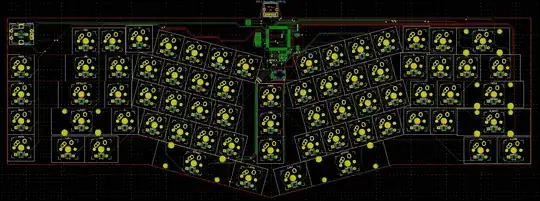
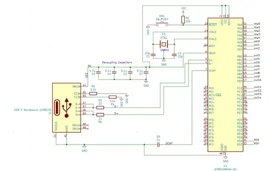
My question is if I designed it correctly or did I mess up somewhere (especially the decoupling capacitors connected to the chip)?

I tried to make it use USB-C (USB 2.0) and as well add a rotary encoder into it.
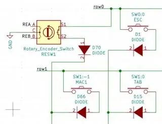
Rotary Encoder Circuit

PCB Image

Chip Circuit

Panchi
  • 33
  • 5
  • 2
    Welcome to EE.SE. Please post the schematic and PCB images into your question. You'll get a better response, we won't all have to follow links to understand your question and your question will still make sense if the links die. Hit the [Edit] link ... – Transistor Jul 06 '20 at 16:48
  • Also, please refer to the following answer for tips on drawing readable schematics: https://electronics.stackexchange.com/a/28255/41856 – DerStrom8 Jul 06 '20 at 16:54
  • The power supply pins are connected via capacitors. Capacitors do not pass DC current, so you might want to fix your errors. See the AVR datasheet as a reference. The schematic is difficult to follow, everything seems to be drawn upside down from the normal rules, i.e. GND symbols point down, VCC symbols point up, etc.. – Justme Jul 06 '20 at 17:07
  • Ok, I'll try to correct the schematic according to the tips on that post. Thanks for the heads up on the bypass capacitors, I wasn't aware of that, I'll correct that as well. – Panchi Jul 06 '20 at 17:11
  • You've put schematics here, but there's still no PCB image. Please do add that too, though you should fix problems in the schematic first. – Hearth Jul 06 '20 at 17:20
  • If I fix the schematic the pcb netlist should correct itself accordingly no? – Panchi Jul 06 '20 at 17:25
  • I've added an 'm' before the ".png" on your encoder schematic to make it 'medium' size. Add a blank line each side of the image tags so that they are separated by paragraphs. Otherwise you get weird word-wraps. – Transistor Jul 06 '20 at 17:44
  • The netlist can be fixed automatically, sure, but the routing you'll have to do over again. – Hearth Jul 06 '20 at 17:49
  • I don't mind rerouting, it should not really interfere with the routing of the switches that much either way – Panchi Jul 06 '20 at 17:50
  • 3
    The crystal capacitors as missing a ground. – Justme Jul 06 '20 at 17:55
  • On the pcb or the schematic? – Panchi Jul 06 '20 at 17:56
  • @Cisco does it matter? The caps are still missing the ground. And the AVR is not powered correctly, you only give it power from USB to the UVCC pin, and all the rest are not connected anywhere for power. – Justme Jul 06 '20 at 18:05
  • I don't know if it does, as I said above this is my first time doing this. Nevertheless, what should the VCC and AVCC pins be connected to if the power is to be received through USB? – Panchi Jul 06 '20 at 18:18
  • @Cisco I would have to look up that from the datasheet and explain it, while you can also open the datasheet page 242 and look for yourself how to do it. – Justme Jul 06 '20 at 18:28
  • @Justme Oh WOW. From what I can understand in the datasheet it's just connecting the VBUS to the decoupling capacitor net then feeding that to the VCC, UVCC, & AVCC pins on the micro-controller. Thanks for the heads up, I'll keep reading into this. – Panchi Jul 06 '20 at 18:33
  • You will have problems having multiple keys pressed down at the same time if you are using the keyboard for gaming. Arrange the matrix so that you can press the keys you want simultaneously. – Ralph Jul 06 '20 at 22:21
  • 1
    @Ralph how so? The crystal will run at 16MHz and all switches have diodes in order to avoid runoffs,as well as being placed in a matrix. The image with the rotary encoder symbol shows a bit of the matrix as well – Panchi Jul 06 '20 at 23:09

0 Answers0