17

I wanted to use my cheap battery powered single-channel oscilloscope or my Rigol 1054Z to see the 120V AC mains signal in my house. No particular reason, just curious.

I at least knew enough to not just blindly stick the probe in the wall socket so I got on YouTube and found a lot of information, some of it contradictory. So taking what seemed like a reasonable approach, I built an "isolation transformer" from an old wall wart I had laying around. (Yes, this was an actual transformer and not just a switching power supply.) Now I'm wondering if this is actually a safe approach.

Upon opening the case, I saw the transformer and a small circuit board with a full bridge rectifier. So I removed the circuit board, which left me with just an AC - AC transformer. Using my DMM, I measured 115 VAC in and 9.9 VAC out. I then soldered the two leads from the transformer to two banana jack ports. There was plenty of room in the case to drill holes and mount these so they can be accessed externally. See the attached picture.

I tried this out with my battery powered oscilloscope and got the expected results. The 9.9V signal was a clean sine wave at 60Hz and I didn't fry anything or die, so I figured that was a success. My questions for you - Is this safe? Can I hook it up to my mains-powered Rigol? Or is there an important point I've missed? Thank you for your help.
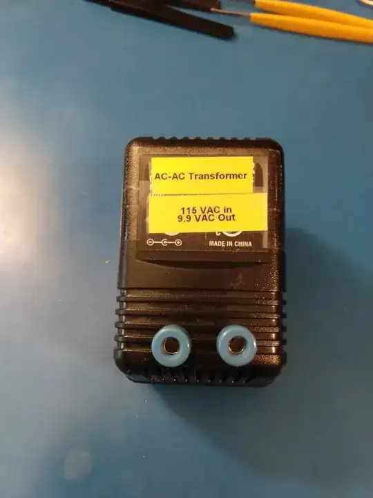
Wall wart converted to isolation transformer

Brad M
  • 181
  • 1
  • 4
  • 3
    Welcome. It is safe is measured isolation is good. The compromise is in linearity. At 80 VAC on the line the transformer will show a larger drop. This is due to the magnetics of the transformer needing a minimum current to magnetize the silicon steel core. –  Jul 04 '20 at 02:04
  • 3
    Actually, if you know what you're doing it's "safe" to just stick the scope probe into the wall outlet. (Consider that O-scopes have been used for easily 80 years to measure voltages in vacuum tube radios, where the voltages may be in excess of 200v.) The "trick" is to use a probe with the proper impedance, and to not stick the ground probe into the "hot" slot of the wall outlet. – Hot Licks Jul 04 '20 at 20:59
  • 1
    @HotLicks As an occasional oscilloscope user I wondered about that as well: What prevents the OP to simply display the voltage over time between the two outlet poles? (Provided the osci can handle the voltage -- that will be stated in the manual and the type label.) Just make sure to not touch any unisolated parts, as always. The transformer will have all kinds of influence on the signal, most likely filtering out high-frequency ripples because of the impedance. – Peter - Reinstate Monica Jul 05 '20 at 12:55
  • 1
    @Peter-ReinstateMonica You would need two probes to do that. You can do it with two probes (at least theoretically) and the oscilloscope's math function to subtract them. But most people will try to do it with one probe, with a 50% chance of frying their oscilloscope. (less if a GFCI breaker is installed) – user253751 Jul 05 '20 at 23:30

4 Answers4

11

That looks like a good safe project to me. You might consider checking the voltage between the 9.9 V terminals and earth. You will probably find some random voltage perhaps even 115 volts. Connect a 115 volt light incandescent bulb between the 9.9 V terminal and earth. With that connection, the voltage across the bulb should drop to nearly zero. That should demonstrate that there is some small leakage current through the transformer due to capacitance between the primary and secondary winding.

  • As you thought, there was some random voltage between each 9.9V terminal and earth. One terminal was 2.9 VAC and the other was 3.3 VAC. With an incandescent bulb in place, that did drop to zero. Thanks for the suggestions. – Brad M Jul 04 '20 at 04:24
10

From your description, it sounds like you've made a safe isolated source of 9 VAC.

To verify that the output is isolated from the AC Mains, you could measure (with the thing unplugged!) the resistance between the mains terminals and your output terminals - there should be no continuity (inifinite resistance) between the mains pins and the 9 VAC jacks.

Peter Bennett
  • 57,014
  • 1
  • 48
  • 127
  • 1
    I confirmed there is no continuity between the mains plugs and the output terminals. Thanks for your suggestion. – Brad M Jul 04 '20 at 04:27
2

and found a lot of information, some of it contradictory.

Some people take a more paranoic approach to safety than others. Also some scopes are more suitable for mains measurements than others.

In general there are three main issues when using a scope directly on the mains.

  1. Scopes are normally referenced to mains ground, so if you hook your probe ground lead to mains neutral you will create a neutral to earth fault which will trip RCDs/GFCIs and could potentially melt wires. You can get around this by just measuring with respect to ground. It's probably close enough and you can always measure the neutral and subtract.
  2. Voltage ratings, many scopes have too low a voltage rating for mains power. You can work around this with an attenuated probe.
  3. The thing that many people forget, overvoltage categories. Many scopes are only "Cat 1" which are not suitable for direct connection to the mains. For connection to mains power from a domestic outlet you want at least "Cat II". To fix this you really want an isolated probing soloution.

Your transformer solves all of these issues, and it is safe to connect your scope to it's output (secondary circuits of normal mains transformers are considered CAT 1). However it may well distort your results.

The proper solution is a high-voltage differential probe, but such a device is out of the price range of the casual tinkerer.

Peter Green
  • 21,158
  • 1
  • 38
  • 76
1

You are on the right track. There one thing to watch is the ground on your scope is not "ground" once you isolate it. You can easily get line voltage on the case of your scope since it is the point your probe ground is attached to.

user256983
  • 11
  • 1