I'm trying to convert +/-12VDC to +/-24VDC to power a DC motor in both directions. I've tried using a step-up converter like this one, but when I feed it -12VDC, it doesn't output anything. Is there an electrical component that will output +24VDC when fed +12VDC and output -24VDC when fed -12VDC? Total noob here just trying to motorize a skylight with a chain actuator, so please excuse my limited understanding.
Asked
Active
Viewed 277 times
2
-
2I used to ask this question on job interviews. Google H-bridge. – Jul 02 '20 at 03:20
-
1Yes, one method is to use a H bridge, such as L298N or L293. "Using L293 H-Bridge to drive DC motor with PWM": https://electronics.stackexchange.com/questions/114796/using-l293-h-bridge-to-drive-dc-motor-with-pwm. Cheers. – tlfong01 Jul 02 '20 at 03:37
1 Answers
5
I don't think you need a negative supply - just use a double-pole relay to reverse the polarity.
simulate this circuit – Schematic created using CircuitLab
You probably need a center-off switch to allow you to stop the motor wherever you want - or a separate off/on switch.
(You probably killed the DC-DC converter when you connected it with the wrong polarity.)
EDIT due to OP's comment that the controller outputs +12V or -12V...
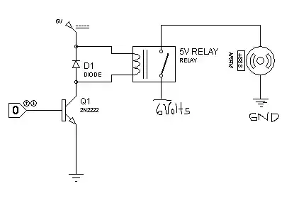
When the controller outputs +12V, the upper relay will operate. When it outputs -12V, the lower relay will operate.
EDIT 2 Changed the upper relay to DPDT to prevent short circuits should both relays somehow become operated at the same time.
Peter Bennett
- 57,014
- 1
- 48
- 127
-
Thanks for the reply, but using a manual switch isn't really a viable solution. In fact, the 12V is already coming from a controller that outputs either +12V or -12V based on commands from an RF remote control. – Numbr Jul 02 '20 at 03:14
-
2
-
Ah, sorry. I thought they were referring to a DPDT switch because I'm clueless. Thanks for the clarification. – Numbr Jul 02 '20 at 05:00
-
1@Numbr: I was thinking switch, but wrote relay when I did the first schematic. The second schematic with two relays should work, if I understand your requirements. – Peter Bennett Jul 02 '20 at 05:17
-
Yes, you understood it perfectly. And, I believe I kinda understand the schematic. So, when the controller is outputting +12V, the diodes will only allow current to flow to the top relay which closes the +24V circuit, and when the controller is outputting -12V the diodes will only allow current to flow to the bottom relay, closing the -24V circuit. Is that correct? – Numbr Jul 02 '20 at 05:50
-
1Better hope the timing works out well on the relays so they don't short the 24V supply momentarily. Also I think if the control signal is suddenly *removed* the coil current *may* circulate through both relays. – user253751 Jul 02 '20 at 10:50
-
Yea, I'd make sure those relays are mechanically forced together (use 1 relay with more poles for both functions) or that one always opens faster than the other closes. – Mast Jul 02 '20 at 11:04
-
1
-
1@Numbr: You only need a single 24 volt supply. The upper relay connects that supply to the motor with one polarity. The lower relay connects the supply to the motor with the opposite polarity. – Peter Bennett Jul 02 '20 at 15:42
-
@Peter: Right, I think got it. The second relay "flip" the wires going to the motor, so that changes the polarity from + to -. Now, to properly source the components, the motor say it has a "working voltage" of 1A, but the documentation says it has a max of 40W@24V. With that in mind, would this relay work? https://www.amazon.com/gp/product/B07SXH846H I understand that I won't need 2 of the pins, since I'm just doing a single throw, but I can't seem to source DPST 24V din mount relays. (I thought din mount would be nice for mounting 6 of them in a structured media panel). – Numbr Jul 03 '20 at 03:17
-
-
1That relay looks fine - I'd go with the 10 Amp contact rating. Double-throw relays are much more common than single throw. – Peter Bennett Jul 03 '20 at 04:30