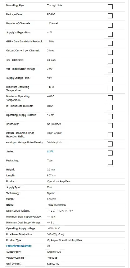
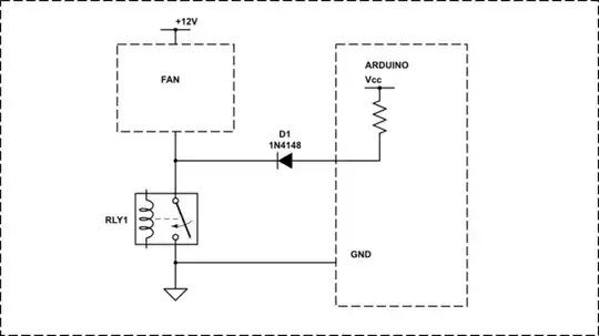
Ok, so I am designing an amplifier using an op-amp to produce the same undistorted output sinusoidal wave across a 2Kohm load as that of the common emitter amplifier shown in the attached picture. I have researched online on what specific op-amps I can use and cannot decide whether I should use an LM741/A or LF351 op-amp. The other pictures attached are the datasheets for both op-amps. Any advice on which op-amp I should use? That will be greatly appreciated.


Asked
Active
Viewed 759 times
1
Wetyyjs
- 11
- 3
-
[Reasons not to use a 741 op-amp](https://electronics.stackexchange.com/questions/304521/reasons-not-to-use-a-741-op-amp/304522#304522). – Andy aka Jul 01 '20 at 14:30
2 Answers
1
You might want to start by comparing the slew rates. A 50 kHz 25 Vpp waveform requires 8 V/us. One opamp offers 16 V/us, the other 0.5 V/us. So one is just marginally suitable, the other entirely unsuitable.
However, there are plenty of other reasons to avoid 741.
Neil_UK
- 158,152
- 3
- 173
- 387
-
Oh yes I just noted the differing slew rates of both op-amps. Is there any other type of conclusions I can come up with when comparing other parameters such as the typical gain-bandwidth product (GBW) and the saturation voltage (Vsat) in conjunction with the dual supply voltage (±VCC)of the op-amp? – Wetyyjs Jul 01 '20 at 14:45
-
@lilboy24 You could compare these two amps for this job on other things, but what's the point? Once one is disqualified, then it's disqualified. If you're looking at other amplifiers, or other spec requirements, then of course you'd check output voltage and current, GBW, input bias, input offset, voltage noise, current noise, suitable package, cost, supply voltage and current, thermal management, any of which might disqualify the amplifier for your application. Have a look at the OP275, my favourite opamp. – Neil_UK Jul 01 '20 at 16:11
-
True. Was just wondering how I can compare other factors such as GBW, input bias, the input offset when choosing between the op-amps beacuse I am not really too sure myself. The slew rate was the only one I could properly understand how it should affect my decision. Would appreciate it if you could explain some of these factors – Wetyyjs Jul 01 '20 at 18:17
-
If you have a specification for the result you want, ie DC accurate to 1 mV or to 10 mV, then you have a basis on which to compare their input offset voltages. If you don't have a specification, then you don't, and can simply flip a coin. Same for all the other parameters. Your application gave a frequency and an amplitude from which a slew rate could be calculated. It didn't give anything from which noise, or offset, or bias could be calculated. – Neil_UK Jul 01 '20 at 19:54
-
How did you calculate that the waveform requires 8V/us? I used the formula Fmax=SR/2pi*Voutpeak. Unclear on that – Wetyyjs Jul 02 '20 at 06:14
0
You're near the limit for Output voltage swing with LF351.
With a \$\pm 15V DC\$ supply, typical output swing is \$\pm 12V\$.
You'll need to power the opamp with rather high voltage DC supplies to achieve 25V p-p output. To meet your requirement, you'd likely want higher supply voltage, but the absolute upper limit is \$\pm 18V\$:

Not even going to contemplate using a LM741 @ 50 kHz.
glen_geek
- 23,591
- 1
- 22
- 50
-
Understood, what other reasons I should choose LF351 over 741 by comparing parameters such as its GBW and Vsat? I want to know other factors. – Wetyyjs Jul 03 '20 at 09:27
-
The simple transistor amp you're replacing doesn't require perusal of too many other opamp specs. You might look at power dissipation, if you're operating in a hot environment - but that applies to any opamp. – glen_geek Jul 03 '20 at 12:09
-
I see. Is there a way to derive the Vsat of the op-amp? Cant seem to find anything in datasheets – Wetyyjs Jul 03 '20 at 12:54
-
Just to clarify, so a +-18V supply voltage is suitable to achieve a 25V p-p? – Wetyyjs Jul 03 '20 at 15:57
-
You have a little range to play with. \$\pm15V\$ gives you 24V output pin swing (if you're lucky). So you need more than \$\pm15V\$ supply....but *never more* than \$\pm18V\$. Can you ensure that your supply never exceeds \$\pm18V\$, even for a moment? The DC supply should also not sag under load - its equivalent Thevenin resistance should be small. At 50kHz, large capacitors on the supply may help. I'd want DC supply to be close to \$\pm18V\$, and look closely at its error budget. – glen_geek Jul 03 '20 at 16:10
-
If a DC supply of \$\pm15V\$ guarantees a swing of 10V into 2k load, then you might assume that 5V is dropped inside LF351. With a higher supply of \$\pm17.5V\$, this same 5V overhead gets you close to a swing of 12.5V at the output pin. I'd want a bit more than \$\pm17.5V\$, but never at any moment more than \$\pm18V\$. That's a tight spec on the DC supply. – glen_geek Jul 03 '20 at 16:23
-
Ahhh I see but what is the reason for wanting a voltage a bit more than +-17.5V ? – Wetyyjs Jul 03 '20 at 16:27
-
I've extrapolated that 5V overhead directly - that's not fair because output current and peak current will be higher when driving that 2k load with 25v p-p instead of 20v p-p. You're right - the spec sheet is a little sparse regarding the overhead @ various DC supply voltages, but you can be assured that you need a bit more overhead than 5V. – glen_geek Jul 03 '20 at 16:41
-
So what do you suggest the supply voltage be? And what is the value of Vsat, is the output swing equal to Vsat? Because an undistorted output waveform is desired and the voltage swing should not be more than Vsat – Wetyyjs Jul 03 '20 at 16:46
