3

I have a question about a symbol in front of a MOSFET gate.

The circuit that I am analyzing transforms almost ~311 V filtered and rectified DC to 48V DC. In images, I saw a symbol that is in green box. It looks like an inductor but there is no value on the schematic. I don't know what it means.

enter image description here

enter image description here

What's with the MOSFET is in this link.


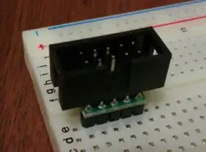
I took a photo of the real circuit. As this answer says, it is a ferrite bead, yes. You can see it connected to the MOSFET's gate pin.
enter image description here

JRE
  • 67,678
  • 8
  • 104
  • 179
GuneyBoss
  • 55
  • 7

1 Answers1

6

It is a ferrite bead that goes on the gate terminal to kill RF oscillations.

JRE
  • 67,678
  • 8
  • 104
  • 179
V.V.T
  • 3,521
  • 7
  • 10
  • But if it is, Must be a name, value or sth.? – GuneyBoss Jun 18 '20 at 13:33
  • 1
    https://en.wikipedia.org/wiki/Ferrite_bead – V.V.T Jun 18 '20 at 13:54
  • Thank you for your answer. I understood now. – GuneyBoss Jun 18 '20 at 13:57
  • Are you 100% sure? Do you have any supporting references for that? I thought about that, but to be frank, I've never seen this symbol used for a bead. I've found [this](https://electronics.stackexchange.com/a/243098/19375) and it's similar, but not the same. Also, I wouldn't expect a ferrite bead in this place. The current leakage is specified for 0.1uA, would a ferrite bead make any difference for this? Or is it for the charge/discharge current of gate's internal capacity? EDIT: Ooh, you meant **RF** oscillations.. – quetzalcoatl Jun 19 '20 at 08:55