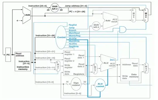
I am trying to include BNE instruction in the following circuit without introducing a new control line. I have thought of many possible ways like adding muxes or and gates etc to implement it but after implementation, a problem always occured with any of the three instructions, PC+4
, BEQ
and sometimes BNE
itself. Now I need a little advice from the experts on how can I implement bne
without introducing a new control line.Here is the circuit:

- 168,369
- 17
- 228
- 393

- 181
- 2
- 2
- 7
-
I am not an EE, but how difficult would it be to convert the zero signal into a condition satisfied/branch taken signal? Obviously, the ALU and its control would be more complex, so that just seems to be shifting complexity around--again, I am not an EE. (BTW, I think some early MIPS implementations performed the branch condition evaluation in separate logic and performed the branch target calculation in the ALU.) – Dec 06 '12 at 17:55
2 Answers
The MIPS architecture you pictured above already includes the required hardware for the BNE instruction.
The two register numbers which are part of the BNE instruction are passed into the Register File which then passes the data to the ALU. If they are equal then the zero flag is set. The instruction decode unit determines whether the branch flag is set based on a whole bunch of control signals which are already present (the aforementioned 0 flag, and a bunch of bits in the instruction opcode). Then the next address for the program counter is calculated based on the ALU on the top which handles adding the offset address to the current address.
Many people have implemented this instruction in the existing MIPS hardware so I am very confident you do not need additional control signals. For more detailed information you can look at the MIPS instruction set and architecture implementation. Here is one such example done in VHDL.

- 4,167
- 3
- 31
- 40
-
2Actually, if you look at the VHDL, you'll see that the control unit actually has TWO signals to convey what is represented schematically as a single "branch" control signal: there are separate "branch" and a "branch_ne" signals. – Marshall Eubanks Apr 10 '14 at 00:53
Let your main control produce the following ALUOp signals:
Notice that the ALUop code 11 is not used, thus BNE can be defined when ALUop=11, then the ALU control input would be 1110 which would need to also do subtract (same as 0110). Now in the case of bne, we know that ALUop will be 11 and for the PC to be set, the 'zero' signal should be deasserted (meaning they aren't equal).
So now it should be obvious that we can use the following logic to determine the result of bne: ALUop1 AND ALUop2 AND ~('zero')
This will be asserted when PC should be set based on the output of a bne operation. The output should be used to control the same mux as the AND gate that is already in your diagram.
My answer is based on the book "Computer Organization and Design" by Patterson and Hennessy.

- 40
- 5