2

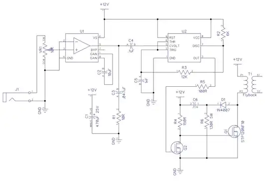
I was a backer of an early Kickstarter project, and now the project leads have dissapeared. Before they left, they offered some advice to fix some of their faulty units. Here's a picture of the project in question:

enter image description here

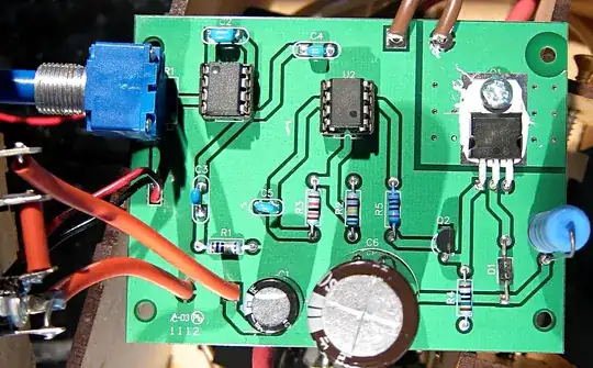
And the only help I have is "Too much current for the UF4007 to handle; it's only rated for one amp." (The UF4007 is part D1 in the board, above: datasheet) and a link to a new part which looks to be an "8A, 600V STEALTH Rectifier".

enter image description here

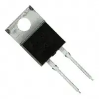
I got the replacement parts, and they look like MOSFETs, but are much narrower than the only diode I see (D1). I could bend the legs out, but because they're flat metal, they don't bend easily. What should I do?

Edit:

Like Madmanguruman says below, it's the current that is killing it. Couldn't I just replace the failing diode with one that has a higher rating? How about this UF2007 that is rated for 2A instead of only one?

Edit2:

Here's a link to the original assembly instructions: http://xwl.me/plasmaspeaker/

Eric Falsken
  • 361
  • 2
  • 5
  • 13
  • Kludge the bigger rectifier instead of D1. Bend the legs carefully if needed. Observe the polarity. If the new rectifier gets too hot, add a bolt-on heat sink. – Nick Alexeev Dec 05 '12 at 04:22
  • Ok, so I got the UF2007 diode and put that in. I got an arc, but it is quite unstable at lower output levels. And at higher levels, it burns instead of arcing. So at this point, I'm going to say that the UF2007 did NOT fix the problem, although it DID fix the circuit. I'm not sure what's wrong with it, probably the whatever rate or delay or leakage. – Eric Falsken Dec 11 '12 at 05:36

2 Answers2

3

Here is the schematic for that circuit board:

enter image description here

As you can see, there is only one diode in the whole circuit, and it's going to be pretty abused by the EMF collapse of the flyback.

So your replacement diode should replace D1. Kludge it in however possible.

Connor Wolf
  • 31,938
  • 6
  • 77
  • 137
  • Um, the UF4007 is rated for 1kV whereas the stealth diode is rated for 800V. The EMF isn't what's killing the part, it's current (according to the original poster and the reddit comments). Furthermore, I have a hard time believing that a well-designed flyback that's only switching 12V could smoke a 1kV diode due to voltage stress. If that were the case, the 800V replacement should smoke faster than the original part (stealth or not)... – Adam Lawrence Dec 05 '12 at 11:11
  • Why not just find a diode that is rated higher? Do they come any higher? – Eric Falsken Dec 05 '12 at 21:42
  • @EricFalsken - Absolutely! You can buy diodes in about any current handling capacity you can imagine. – Connor Wolf Dec 05 '12 at 23:07
  • @Madmanguruman - I don't think I ever claimed that he was exceeding the *voltage* rating of the diode. It's most certainly an issue with the EMF collapse driving short, high-current pulses through the diode, causing it to fail. – Connor Wolf Dec 05 '12 at 23:08
  • @fakename Fair enough. I'm used to seeing EMF in the context of voltage as opposed to the stored energy in the field of the flyback transformer. (Both definitions are valid.) – Adam Lawrence Dec 06 '12 at 01:29
  • @FakeName +1 for gigging up the schematic. BTW, notice that U1 is a 555. I'm guessing, the circuit runs as a class D(ish) amplifier. – Nick Alexeev Dec 06 '12 at 19:06
  • @NickAlexeev - Not quite. It's more of a frequency modulated spark-gap. – Connor Wolf Dec 06 '12 at 22:51
2

You could go for the new part (it will be easy to kludge it to fit as Nick says), but if you have more than one of the UF4007s, then you could put them in parallel to increase current handling capability (e.g. use 4, and solder all leads together in the same polarity, just trim 3 of the diode leads shorter - twist around the 4th and solder, then leave the leads long for one to mount through the pads)

As Fake Name says, this is generally not regarded as the best idea (although IMHO I think it will probably work okay in this circuit - I've been wrong before though ;-) ), so ideally the much higher rated diode is the best option for peace of mind.

Oli Glaser
  • 54,990
  • 3
  • 76
  • 147
  • 1
    Paralleling diodes is never a good idea. Unless they're from the same batch, their Vf can be different, which leads to unequal current sharing, and no real improvement in overall current handling capability. Instead of just having one diode fail, you will simply have several diodes fail in sequence. – Connor Wolf Dec 05 '12 at 05:10
  • I know, but it should work well enough for this I think, especially if all thermally linked. The overall handling will be improved still. – Oli Glaser Dec 05 '12 at 05:11
  • I edited to note the parallel problems - I generally wouldn't advise this (in fact I've advised against it here a few times in other answers), but I have used it as a hack in the past for personal projects and it's worked okay (i.e. increased current handling) In the end of the day, one part is better than 4 bodged together anyway I guess... :-) – Oli Glaser Dec 05 '12 at 05:18
  • Fake Name +1. I think this is a bit dangerous approach. – Al Kepp Dec 05 '12 at 22:23
  • @FakeName Could you chime in on [this one](http://electronics.stackexchange.com/a/50749/7036) regarding diodes in parallel? – Nick Alexeev Dec 06 '12 at 21:36
  • @NickAlexeev - As I said, *unless the diodes are of the same batch*, it's generally a bad idea. That link is specifically paralleling the diodes in each rectifier. It's a pretty good bet that all the diodes in a single bridge rectifier are from the same batch, so it's somewhat more acceptable then simply paralleling two random diodes, even if they're the same part number. – Connor Wolf Dec 07 '12 at 03:16