4

The Problem

I have a project using multiple WS2813 ledstrips, one variant which uses a white PCB and one that uses a black PCB. When setting the colors of these ledstrips multiple times, I noticed that the black PCB strips frequently show an incorrect result. Most of the times it shifts the colors by a few leds but it will also change the colors or shift the leds by 10+.

The PCB

The strips are both WS2813 (at least they were advertised as such). I've attached an image of both the strips below.

Image of Black PCB

Image of White PCB

Video Example

The following gifs demonstrate the problem I'm having. Both strip types got the command to set leds 25 to 50 to Red.

Gif of Black PCB shifting
Gif of Black PCB shifting

Gif of White PCB not shifting
Gif of White PCB not shifting

Gif of White & Black PCB on the same data pin. Data is coming from the right, so the shift is always later on the strip.
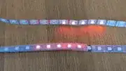
Gif of White & Black PCB on the same data pin

Connections

The strips are connected as follows:

Strip -- Teensy 4.0

+5V -- External 5V

D0 -- Teensy Output pin (i.e. 19)

B0 -- External GND

GND -- External GND

The Teensy is also powered by the external power supply.

The ledstrips are connected in parallel, with every strip on one of the following pins: 19, 18, 14, 15, 17 and 16.

The strips are only connected at the front, not the back.

Edit: Connecting the back to the power supply does not seem to have any effect on the shifting.

The external power supply is an RSP-200-5 (5V, 40A).

Voltage Measures with only 5 leds active

Led #0: 4.99V

Led #60: 4.97V / 4.98V

Led #110: 4.95V (Sometimes drops to 4.84 on the White PCB)

Datasheets

White PCB Led Datasheet

Diagram

Electrical Diagram

Veleon
  • 41
  • 3
  • [What to check for when buying an electronic component or module](https://electronics.stackexchange.com/questions/504044/what-to-check-for-when-buying-an-electronic-component-or-module). Please provide data sheet links. – Andy aka Jun 15 '20 at 10:29
  • How are the LED strips connected? Are they connected one after another as a single long chain, or both directly to Teensy as two parallel chains? How are they powered with 5V, from only from one point, or are both strips powered from both ends? – Justme Jun 15 '20 at 10:41
  • @Justme, I've updated my post with the information. – Veleon Jun 15 '20 at 10:47
  • @Andyaka, I've added one datasheet. For the other one I'm still waiting to hear from the retailer. – Veleon Jun 15 '20 at 10:48
  • Do you actually mean the black PCB is a blue PCB? – Andy aka Jun 15 '20 at 10:51
  • @Andyaka, the color is black, although it might be a bit unclear in the picture because of the waterproofing. – Veleon Jun 15 '20 at 10:52
  • What happens if you move a black strip to a pin that is currently driving a white strip? Is the transmission ever interrupted? (remember, these depend on accurate timing, and a reset will occur after a low period of >280us... idling high appears to be undefined). Have you counted the LEDs... does the red / pattern ever appear _after_ where you'd expect in the chain, or always before? Have you tried your red test at the close and far ends of the chain? What voltage do you measure at either end, and the middle? Diagrams are helpful, please include one, with long wires clearly marked! – Attie Jun 15 '20 at 10:53
  • That's the datasheet of the single LED, not the strip. And I still have no idea how the power is applied to the strips. If you power the strip only from one end, there might be too much voltage drop at some point. If you use too long or too thin wires, the voltage might be too low to begin with. Have you measured the voltages on the strip, what is the voltage at the point that the LEDs start to go wrong? How much there is ripple and noise on voltage? Any bulk or bypass capacitors on the supply? – Justme Jun 15 '20 at 10:54
  • Yes, as @Justme says, the data sheets for the product are required and not the LEDs. – Andy aka Jun 15 '20 at 10:56
  • @Attie I've added another gif with the ledstrips connected to the same data pin. The pattern almost always appears after the expected location, rarely before. – Veleon Jun 15 '20 at 11:38
  • @Justme, I've added the voltages and a diagram. I do not know how to measure ripple and noise on the voltage, but I do have a multimeter so I'll try to find out if it is possible to measure them with it. – Veleon Jun 15 '20 at 11:40
  • This is most likely a timing issue in the software: If there's a delay, the RGB values are not shifted any further but displayed. Can you show the software you are using? – Codo Jun 15 '20 at 11:53
  • Is it possible that your Teensy is dropping some bits or sending them with incorrect timing? – user253751 Jun 15 '20 at 12:33
  • I found this FastLed issue (which is the library I'm using): https://github.com/FastLED/FastLED/issues/449 I think that this is the issue, but without the datasheets from the retailers I cannot confirm this yet. – Veleon Jun 15 '20 at 12:56
  • @user253751, I thought that at first, but the gif where the data pin is connected to both types of strip confirms that this is not the issue. If it dropped bits then both strips wouldn't work instead of only one type not working. – Veleon Jun 15 '20 at 12:58
  • 1
    Have you got a large electrolytic cap anywhere? Typically, these strips require 10-100uF across the supply at the start of the strip. Without it, you can get unpredictable results – SiHa Jun 15 '20 at 13:12
  • 1
    Is the GPIO reference of the Teensy 3V3 or 5V? – sstobbe Jun 15 '20 at 15:36
  • it is timing, power or bad parts. What have you done to eliminate these possibilities, you need a scope to examine the signal from the controller and check timing, to examine the power along the strip to see if it is dropping as well as the cascaded signal to see if it is dropping or bad timing. – old_timer Sep 23 '20 at 19:52

3 Answers3

3

The Teensy revisions 3+ use 3.3V internally. The pinouts will provide no more than this voltage. The LED, on the other hand, requires 0.7 x 5V = 3.5V as high input.

You need a voltage translator or buffer chip. Any 74ACT or 74HCT logic chip will do. It also helps to connect a 100 Ohm resistor between buffer output and LED data input. See https://www.pjrc.com/store/octo28_adaptor.html for related information.

Carsten B.
  • 339
  • 1
  • 5
0

Typical issue of voltage drop or lack of capacitance.

The led strip does not have a small decoupling capacitor per led or even per few LEDs. You also didnt add a large capacitor to the front.

I see you did connect power to both ends of the led strip. But what is the measured voltage in the middle where the strip is bugging out? For most led strips its recommended to have voltage injected every 2.5 meters.

It could also be a faulty strip. The connections could be bad so the LEDs there are resetting. This could be bad from the factory or someone flexed the strip to an extreme degree and the solder broke.

Passerby
  • 72,580
  • 7
  • 90
  • 202
  • The voltage in the middle is the same as measured with only 1 end connected to the power supply. Currently I think that it's an issue with the timing, as all 200+ meters of black pcb ledstrip have the same problem. – Veleon Jun 15 '20 at 13:43
0

I can see in your pictures that the two strips are not using identical parts. Note the location of the IC inside the LED package. The strip that is not working as you expect may not actually be what you think you bought. There is also the possibility of counterfeit. I suspect if you tried your setup with another strip of the white variety your issue would be resolved.

David
  • 302
  • 1
  • 8