I was thinking about buying a thermistor and a RGB LED and thereby be able to change the light of the LED, but I'm confused by the resistances I see on eBay. I see some of 100 ohm, 10k ohm and 100k ohm. What do these resistances mean, and what should I use for my circuit?
Asked
Active
Viewed 3,900 times
1
-
2Do you have any circuit ideas right now? If you do, then post them. Keep in mind also that there are two types of thermistors: Ones with positive temperature coefficient and ones with negative temperature coefficient. PTC thermistor resistance increases with temperature increase and NTC thermistor temperature decreases. The resistance you should pick depends on the way you actually want to control the LED and as I've said, from the question I can't figure out how exactly you plan to do that. – AndrejaKo Dec 04 '12 at 21:02
-
1Are you trying to change the light intensity or the color with temperature? – Gustavo Litovsky Dec 04 '12 at 21:11
-
What temperatures did you want to be assigned to each colour and was this a home project for a thermometer scale? – Tony Stewart EE75 Dec 05 '12 at 05:22
3 Answers
3
The resistance of a thermistor changes with temperature. In the datasheet for the thermistor there will be a graph that shows the resistance over some temperature range. If you cannot get the datasheet for the termistor, don't buy that thermistor. Digikey has datasheets for everything they sell, but eBay can be hit or miss.
Sometimes the resistance goes up as the temp increases. This is called a Positive Temperature Coefficient, or PTC thermistor. Other times the resistance decreases as the temp increases. This is a Negative Temperature Coefficient, or NTC thermistor.
When a thermistor is advertised as being a 100K thermistor, that means that it has a 100K ohm resistance at some "normal" temperature-- usually room temperature. The datasheet will tell you what the "normal" temp is. Another reason why you should not buy one without the datasheet.
Next is the problem of figuring out how to control the RGB LED with the thermistor. Judging from your question, I am assuming that you're new to electronics. This is unfortunate, as the problem of controlling the LED can be difficult. Especially if you want to control the color based on the temp.
One thing that you likely do NOT want to do is to use the thermistor as the current limiting resistor that is normally found with LEDs. There are several reasons for this. #1 is that the resistance of most thermistors is too high to be practical as a current limiting resistor. Not impossible, just not usually practical. #2 is that thermistors often cannot handle a lot of current flowing through them that is required for an LED. Again, not impossible but you must carefully choose the thermistor. #3 The change in resistance over the required temperature range is probably not right to get the desired look you seek. And the big one is: #4 If you run a lot of current through the thermistor you will actually heat up the thermistor, thus corrupting your temperature measurement.
There are several things you might want to control based on the temp. The main ones are the intensity of the LED and the color of the RGB led. Controlling the color is probably what you want, but it is the most difficult. The reason why it is the most difficult is because the conversion from temp to R, G, and B is not linear (or even monotonic).
The easiest way to do it is with a microcontroller. Use the thermistor as one resistor in a voltage divider and feed that signal to the ADC input of an MCU. Then some software in the MCU reads the temperature and figures out the proper duty cycle for PWM-ing the R, G, and B LED's. I know, this isn't easy-- but it is the easiest way. There are other methods to do this but they are much harder and/or do not provide the best visual appearance.
-
Normally colour is associated with temperature so naturally the intensity if each LED must be done gradually to implement a rainbow scale. Do you think that's what he had in mind? If so how would you implement that with Blue cold, green normal and Red Hot in a linear scale. – Tony Stewart EE75 Dec 05 '12 at 06:04
-
-
I know. It would be Gausian like for Green and half Gaussian for either extreme, Overlapping each curve into R G B. I think the OP is scared to continue. – Tony Stewart EE75 Dec 05 '12 at 06:42
-
@David As an aside would 10-20mA through a thermistor would have a fairly noticeable impact on its temperature? – JYelton Dec 05 '12 at 07:08
-
Just apply Ohms law and 100'C/W, Depends on package size .. but if big it will be slow. They also come in 1 Ohm values.so in effect very much so. – Tony Stewart EE75 Dec 05 '12 at 10:42
-
Although I just remembered an interesting application for using high current ( 1/2W ) in a thermistor and that was used in a fault detection circuit from Fujitsu before Hall Effect and tach sensor output pins were invented. When the fan failed the thermistor would get hot change values significantly and trigger an alarm logic level called "Fan Fail" which could be used to protect a device from catastrophic failure. It was built into the fan bracket and more accurate and faster responding than an overtemp switch mounted on a larger unit. – Tony Stewart EE75 Dec 05 '12 at 10:54
-
1@JYelton It could have a very noticable impact, but it depends greatly on the size of the thermistor and how it is mounted. A thermistor in a TO-220 like package and bolted to a huge engine block might not notice. But a super tiny thermistor that is just floating in the air might heat up by quite a bit. – Dec 05 '12 at 15:11
1
You can use a resistor or thermistor to limit current to an LED. The more current you limit (less current total) the dimmer the LED will be. (I prefer to give LED's constant current and PWM for brightness control, in my applications, but that's another topic altogether.)
First you want to determine the current and voltage characteristics of your LED. Since it's RGB, it will likely have three values for both. Typical LED's have a voltage drop of 2 to 3.2 volts, and often 20mA current.
Once you know these values, you can compute the value for a current limiting resistor for each of the three diodes using Ohm's law (handy online calculator).
That should be your minimum resistance, meaning it allows the LED to operate at its max current, or brightest. Finding a thermistor that matches is what you want. As the temperature changes, you'll want to increase resistance to dim the LED.
You'll have to experiment to figure out what thermistor is best, as some will change more rapidly than others.
You didn't specify if you want the LED to become brighter as temperature increases, or as temperature decreases. Also you didn't specify a source voltage. Both of these will affect what thermistor you should look for.
Edit:
Please see David's answer for more/better information. I agree with him in that a thermistor probably shouldn't be used to current limit an LED. I've played with thermistors before in this fashion, but it doesn't work that well and the ability to dim the LED is pretty limited.
JYelton
- 32,302
- 33
- 134
- 249
-3
Thermistors are rated with different sensitivity scales per degree'C and the room temp value at 25'C which the nominal values you read. 100,10,100K More here on NTC
The active thermal chips are very accurate (1'C) and more suitable as voltage source sensors such as the LM335, which I recommend you consider instead.
**If you drive a RED LED for example with 2V with an Effective Series Resistance of 5 Ohms using a 100 Ohm Thermistor, it will self heat from LED current and not simply a measure of ambient temperature. If it is am NTC, it will drop in resistance causing even more current flow and self heating. If you used a PTC it would self heat and raise the resistance and get dimmer. Thus Thermistors are not intended as Sensors and not current limiters. However, PTC Polyfuses are an except and used as current limiters but not for external temperature sensing. They self regulated resistance usually at 85'C when current limited.*
Now back to my answer to the 2nd part of your question.
An RGB LED is a non linear device approximately, a diode with a series resistance such that the rated Vf at rated current is the sum of both voltage drops. To modulate a voltage using the series resistance of a thermistor with a fixed voltage, it would have to be as low as a few Ohms to rise a few KOhms and these do not exist in room temperature ranges. A thermistor bridge amplifier is needed using an Op Amp or equiv.
However, Voltage sourcing LED's is not a good idea unless you understand the VI curve of each LED. Every LED is slightly different but if you remember the ballpark values it is helpful.
Otherwise current sources are used for design as a standard practise to allow for wide tolerances on voltage with each batch and temperature dependency.
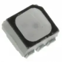
Consider the OVSTRGBB1CR8 PLCC RGB LED
I made a little table now of this LED, which is typical for all RGB LED's but variations exist with P/N and size of chip.
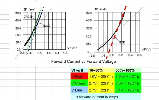
Here you can see the separate voltage V vs I curve. and two linear approximations for low and high current using an arbitrary 50% threshold. The ESR or series resistance, Rs of each LED drops as current increases to rated current.
Note that Vf (blue) = 3.1V + 12Ω * IF [A] for If = 0.025 ~ 0.050 Amp means it has an ESR of 12Ω for currents 25~50mA using a threshold of 3.1V
Since thermistors tend to be much higher resistance values. you can now see it is impractical to use a thermistor to regulate the LED current, but you can amplify a voltage ratio using a thermistor to drive a MOSFET to change the voltage above but that is not very precise. It has been done in cell phones but requires precise awareness of LED VI curves and MOSFET VI curves and their corresponding ESR values.
So let's try a more precise method that does not rely on voltage tolerances.
To regulate brightness PWM is the best precise method.
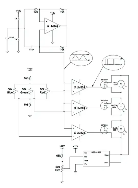
Now to control the brightness using a thermistor instead of a POT you need a "bridge" or resistor ratio circuit to create the voltage you need over the temperature range you choose.
There are many sites and links to show you how to use a thermistor, so I wont duplicate here except to say you need a half bridge circuit with a precision voltage reference.
The module in the bottom is a constant current source which is selected to drive the maximum current and the PWM MOSFET bypasses the LEDS to reduce them to zero current while the entire string stays constant.
Side notes:
When you drive all RGB discrete LEDs together you also get white to the eye, but the spectrum is narrower, so when reflecting it off objects it will give a slightly different shade or Colour Rendering Index(CRI) than sunlight but for light indicators shining on the retina, it can work.
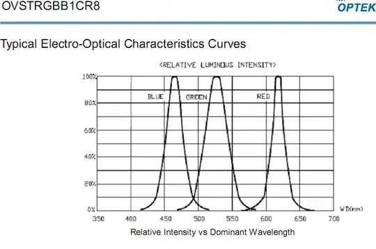
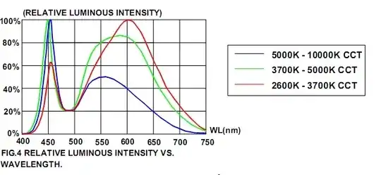
This has nothing to do with your RGB project but it is useful to compare the spectrum of White LEDs with the RGB you are beginning to use.
See in the White LED profiles below how the warm white (3000'K) has more (green & yellow) phosphor added, it absorbs more Blue emission so the overall power radiated is slightly less than cool white.
Note that White LEDs are actually Blue LEDs with phosphors to perform wavelength conversion and yield an apparent white colour so they have a similar VI curve.
When mixing RGB colours note that white is not the same although neutral white or 5000'K is close to a cloudy daylight white.
Speaking of which, have a nice day.
Tony Stewart EE75
- 1
- 3
- 54
- 182
-
1That's quite a lot of information that most likely went straight over the head of the OP. – Dec 05 '12 at 04:42
-
-
There are more basic things than VI curves. In fact, the OP only asked one question in his post and you failed to answer it. "What do these resistances mean, and what should I use for my circuit?" I'm sorry if it seems like I'm always on your case, but your answers would be much better if you just read the question first. – Dec 05 '12 at 04:49
-
-
And that attitude is why this answer most likely went over the OP's head. At least nobody can say that I didn't try to help you improve your answer. – Dec 05 '12 at 05:01
-
If you wanted to help you could have added the many thermistor links but instead... but chose otherwise. I answered his 2nd question rather than the 1st . – Tony Stewart EE75 Dec 05 '12 at 05:02
-
I added my own answer. And to appear unbiased, I removed my downvote of your answer. Good luck. – Dec 05 '12 at 05:24
-
It seems we have to make a lot of assumptions about the OPs motive, scope, awareness and intent. THis site is about learning and we don't even know if he is bent on learning thermistors or just wants a color LED thermometer which is best done without thermistors. – Tony Stewart EE75 Dec 05 '12 at 05:25
-
@Richman I thought your answer was interesting and provided a lot of information, but I couldn't help feeling sorry for the OP. I too got the feeling the OP is not quite ready for this amount of information. Just my 0.02. – JYelton Dec 05 '12 at 07:05