Or we can use 2n700 series, 3906 and 3904 bjts. My aim is 10W, gain 100-1000 (adjustable), 50hz-20khz amplifier by using this basic components.
-
1By paying attention to the output stage biassing to eliminate crossover distortion. – Jun 13 '20 at 18:01
-
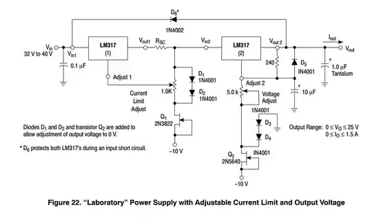
1Look, REDi, you are trying to use \$\pm 50\:\text{V}\$ rails into an \$8\:\Omega\$ load. This strongly suggests you are looking for a maximum of about \$125\:\text{W}\$ into the load! (Not necessarily, but probably given the magnitudes here.) With just two BJTs??? Seriously? Just the drive requirements alone will be on the order of 10% of that. Do you seriously imagine an LM358 opamp can do that? It's not just a biasing problem, for gosh sake. It is a complete mental disconnect in design. You've a few things to learn between here and there, I fear. What're your real goals? – jonk Jun 13 '20 at 18:08
-
[Here's](https://i.stack.imgur.com/4nDGQ.png) an example of a \$50\:\text{W}\$ amplifier designed by a professional (Douglas Self.) You can hog out the diff-amp pair and its collector load on the left side and make a few adjustments to see how something *might* look, if you designed it for the purpose. You won't be using the LM358, though. Also, you have some filtering going on in your design, which means we need to know a lot more about your goals to say much else. But that picture will give you an idea of what your output stage should look like. – jonk Jun 13 '20 at 18:19
-
Thank you @jonk but I need max 10 W and 10 V. my input signal is 10mV. My circuit works but there is a little bit distortion, ı have overcome the distortion as we se in this picture :) – REDi Jun 13 '20 at 18:24
-
@REDi You can achieve \$10\:\text{W}\$ into \$8\:\Omega\$ with \$\pm15\:\text{V}\$ rails. Why are you using \$\pm50\:\text{V}\$ ? Also, what's the function of all those opamps??? – jonk Jun 13 '20 at 18:29
-
İt doesn`t matter, ı agree with you, Lets use 15, This opamps circuit is a butterworth circuit that makes filter my signal between 50-20kHz. – REDi Jun 13 '20 at 18:32
-
@REDi Do you need a multi-pole Butterworth? Usually, this is handled differently in audio amplifiers, using added methods to introduce zeros and poles, accordingly. You might which to look over this [post from me](https://electronics.stackexchange.com/a/503581/38098). I don't know if it will help. But perhaps. It avoids the use of an opamp, though. (You can still achieve Butterworth designs using only BJTs, too. But I'm not recommending it to you.) The problem with my link here is that achieving \$A_v\approx 1300\$ isn't appropriate for that topology. It would need some additions. – jonk Jun 13 '20 at 18:35
-
Hey @jonk , There is a mistake, I have used 15 V and My signal was distorted.Only 50 V, it works like in the picture – REDi Jun 13 '20 at 18:36
-
May I suggest an ol' reliable TDA2030, or similar? Typically, you only need a few other external components, and you're likely to get much less distortion, though maybe not too many zeroes. – a concerned citizen Jun 14 '20 at 14:40
3 Answers
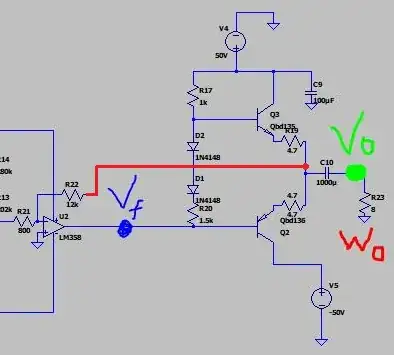
You can try something like this: -
It will certainly reduce cross over distortion. Try it in your simulator.
However, you have another problem - either your circuit or my modified circuit can only use a maximum voltage of +/- 18 volts for the LM358 (in the real world) and this means that the maximum peak-to-peak signal it can produce at node Vf is around 30 volts peak-to-peak and, given that your output stage is a push-pull emitter follower, the maximum output voltage will also be 30 volts peak-to-peak.
Given also that your output stage has +/- 50 volt rails, you may be expecting some form of magic to make your output signal bigger than 30 volts peak-to-peak. That magic won't happen. Also, you'll be lucky if the LM358 can drive anything like the current needed into the bases of the output pair when connected to an 8 ohm load.
- 434,556
- 28
- 351
- 777
-
I tried your connection which is your draw but ı did not observe the sinusoidal signal, it was triangular form. In a nutshell, I wanted to design an amp that could power 10w and gain gain between 1000 and 100, with a 50hz and 20khz transition band frequency.It has worked bu it has distortion a little bit as wee see in first picture I have to handle it. my input signal is 10mV. – REDi Jun 13 '20 at 18:22
-
-
-
Have you traced the signal back to an earlier stage to see if the distortion is present there. The LM358 is a very slow device for audio and has a limited slew rate. – Andy aka Jun 13 '20 at 19:07
-
Of course, the distortion occurs at the point after the 4th opamp before the 675 ohms resistance. Up to that point, the signal reaches perfectly – REDi Jun 13 '20 at 19:30
-
-
-
Look at the datasheet of as lousy old LM358 dual opamp. it is made for low power so it jhas its own crossover distortion and has a poor slew rate causing trouble above only 3kHz. that is why it is never used for audio. – Audioguru Jun 13 '20 at 20:42
-
@REDi use a faster op-amp is realistically the only option without going to an all transistor amplification system. Go for something like..... the AD8571 also available as a quad op-amp. But you still haven’t overcome the power rail problem and the AD8671 can only run from a supply rail of typically +/- 15 volts. In other words no better than the 358 in this respect. – Andy aka Jun 13 '20 at 21:09
Look at the datasheet of as lousy old LM358 dual opamp. it is made for low power so it has its own crossover distortion and has a poor slew rate causing trouble above only 3kHz. That is why it is never used for audio. The old LM358 has a maximum allowed supply of plus and minus 16V. The 4.7 ohm emitter resistors for the output transistors is throwing away half of the output power so the maximum output will be only about 5W. Why do you have so many filters? Use more modern opamps that are made for audio like an OPA2134 dual. Of course some negative feedback must be added from the output.
- 3,894
- 5
- 8
In addition to the excellent advice from @Audioguru
The LM358 is poor but I assumed it was all you had.
Your impedance needs to be low bass damping error.
The max current of each stage determines the incremental impedance ΔV/ΔI=Zout (f) which rises with f due to a reduction in loop gain for error feedback.
Loop gain feedback will reduce from the emitter Rs by feedback gain BW.
So for 8 ohm Load and 200 Ohm open loop output impedance of Op Amp a Darlington worst case gain of 2000 roughly reduces 200 to 0.1 Ohm with a Damping factor of 80.
For a 50V supply you would need a 3 stage Darlington.
So I simulated it with +/-24Vdc using a maximum of +/- 20Vp triangle input unity gain and +/-24V with LM328 with +/-4V drop from Vcc,Vee
You must also pay attention to DC current and power dissipation of every part.
This can produce 50 W pk and 16 W avg with +/-24V
- 1
- 3
- 54
- 182


