0

I have a joystick that I wish to connect to my Arduino uno. However, there's no VCC or 5V or GND pins to connect to. I do see a COM pin, but I'm unsure how I should wire that to the Arduino. My objective is to take an input that determines whether LEDs should be emitting light or not.

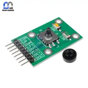
I can't find any model number on the PCB or on the listing where I bought it from. The only information provided on the listing:

user5423
  • 55
  • 6
  • How should we know by just looking at the picture? We can only guess. Please put a link to datasheet or manual. Or at least tell the make and model of the device. – Justme Jun 11 '20 at 15:09
  • I'm guessing it needs pullup resistors – DKNguyen Jun 11 '20 at 15:10
  • @Justme Please see the new edits, Thank you – user5423 Jun 11 '20 at 15:27
  • the device consists of seven switches connected to a common line ... apparently, you did not read the documentation you included ... it talks about Vcc and GND – jsotola Jun 11 '20 at 15:37
  • 1
    [What to check for when buying an electronic component or module?](https://electronics.stackexchange.com/questions/504044/what-to-check-for-when-buying-an-electronic-component-or-module). – Andy aka Jun 11 '20 at 16:15

2 Answers2

2

The device is likely a just a set of passive switches. There is no "VCC".

  • "COM" would be the "common" pin. You can supply it with a voltage (5V for example) and then each signal (UP/DOWN/etc) would go to something like inputs on your microcontroller.
  • You could also use it the other way around by connecting COM to ground, and the signal pins could have their own pull-ups.

enter image description here

Bort
  • 5,102
  • 5
  • 31
  • 56
  • 1
    You will probably also need pull-down or pull-up resistors in the MCU inputs, or enable internal pull-ups/downs in the microcontroller. – Peter Bennett Jun 11 '20 at 18:41
  • Sorry for my late reply. I appreciate the answer, If you have time, could you briefly explain pull-down and pull-up resistors in layman's terms? – user5423 Jun 18 '20 at 12:50
  • @user5423 - If you look at my diagram above, you will see there is 5V on the left side of the switches. However, between the switches and the microcontroller inputs, there is no voltage. You might think that equals "0V", but since it's not connected to ground, there is actually no particular value. The voltage is "floating". This can be problamatic, as the reading on the micro may be LOW some of the time, but it can actually fluctuate due to things like radio waves or your hand being near it. A "pulldown" is a high-resistance resistor (eg: 100kΩ) that "pulls" the voltage down to 0V (LOW). – Bort Jun 18 '20 at 13:37
  • @user5423 - The value of the resistor must be high so that if the switch is closed, the 5V can"override" the 0V. Note that many microcontroller have optional built-in pullup or pulldowns. In the case of Arduino Uno, the input pins have built in pull-ups. You can enable them by setting the pinmode to INPUT_PULLUP (instead of just PULLUP). When you do that, the pins will "rest" at 5V, and to change the reading, you must pull the inputs LOW. (This is opposite of how we typically think). Thus instead of connecting 5V to the left side of the switch in the diagram, you would instead connect ground. – Bort Jun 18 '20 at 13:40
2

It is apparently just a group of switches with one side of each switch connected to a common pin, like so:

schematic

simulate this circuit – Schematic created using CircuitLab

You may connect the common pin to Ground of Vcc, whichever is convenient, and add pull-up or pull-down resistors on the MCU pins as needed.

Peter Bennett
  • 57,014
  • 1
  • 48
  • 127