I read an introductory textbook to understand this but it doesn't tell the reason behind it. Is that because the JFETs require much less voltage to operate comparing to BJTs and one needs to drop voltage at the input? I'm a bit confused.
Asked
Active
Viewed 1.7k times
7
-
1We have a tradition of accepting answers to questions here. Some of your previous questions have good answers with no explanation from you on why they aren't acceptable. You should try to rectify this issue by accepting some answers or editing your questions to make it more obvious why available answers aren't good enough to be accepted. – AndrejaKo Dec 03 '12 at 19:03
-
1thats mostly because i dont feel eligible enough to judge the answers apart from trying to learn. but I'll be more careful. – user16307 Dec 03 '12 at 19:08
-
OK. That's good enough. If you don't feel that you're able to choose good answer, then don't feel pressured to do so. – AndrejaKo Dec 03 '12 at 19:20
3 Answers
11
It's due to the way they operate - JFETs (and MOSFETs) are Field Effect Transistors, so the way they control the current is different (to a bipolar transistor - FETS are unipolar devices)
The gate to source impedance is naturally very high with these components - you can think of it a bit like squeezing a hose to stop the water flow - there is no actual current/water flow into the "hose".
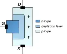
A JFET is a depletion device - it starts out with a low resistance between drain and source, and then the gate-source is reverse biased to turn the FET off. Since the gate-source is basically a diode, you have almost zero current flow (just a bit of capacitance to charge up) With a JFET, if you foward bias the gate the impedance will be low, just like a normal diode.
With a MOSFET you can have both depletion and enhancement devices, due to there being a layer of oxide in between the bond and the substrate. This means the impedance is high no matter which way you bias the gate, since there is no DC connection between the gate and channel. The input impedance at the gate can be 100s of Megaohms, again a small capacitance is present which needs to be charged up in order to switch the MOSFET on.
Note that the above is a little simplified, there are operating conditions to watch out for as with other components (for example in a MOSFET the gate-source breakdown level is rather low, e.g. 10-15V. Also FETS are very sensitive to static discharge damage)
Oli Glaser
- 54,990
- 3
- 76
- 147
-
"it starts out open" --- do you mean "open" as in there's an open circuit between source and drain? – The Photon Dec 03 '12 at 19:11
-
I think I have fundamental problem understanding the term "input impedance" here. Can you give me an example of a circuit used in real world application which has "high input impedance" and composed of JFETs? I just cannot make a bridge between these theoretical explanations and a real life application :( – user16307 Dec 03 '12 at 19:13
-
@ThePhoton - No, I mean there is low resistance between source and drain (i.e. no depletion region) - sorry bad wording, I will edit it. – Oli Glaser Dec 03 '12 at 19:15
-
@user16307 - here is a nice little [project](http://amasci.com/emotor/chargdet.html) that relies upon the FET characteristics. There are many, many uses - another one is in an [electret microphone](http://en.wikipedia.org/wiki/Electret_microphone) – Oli Glaser Dec 03 '12 at 19:21
-
I think if I'm not wrong it is then used for applications where we don't need any input current as in your "Electret microphone" example. And zero current input means "high input impedance"... – user16307 Dec 03 '12 at 19:27
-
1Yes, that's pretty much it - mostly "don't want", rather than "don't need" though. Also, there are other advantages it has over a bipolar, for instance it can be used as a [voltage controlled resistor](http://arxiv.org/ftp/arxiv/papers/0708/0708.3498.pdf) in e.g. a programmable gain amplifier, or a feedback control element for an oscillator. This convenient [pdf](http://www.portabletubes.co.uk/sitefiles/50FETProjects.pdf) gives 50 examples of FET uses. – Oli Glaser Dec 03 '12 at 19:53
5
The reason is because FET devices have (almost) no current flow through their base, and as a result an incredibly high impedance. If you look at current flow through a BJT, notice that the base has current flowing in:
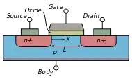
By comparison, in a JFET device current flows only through the drain and source. I've used a MOSFET, but the principle is the same:
Now in a perfect world the FET has an infinite input impedance. This of course is impossible, but it's not unrealistic to find an impedance of hundreds to thousands of megaohms. In comparison, the current through a BJT means that the impedance will be in the KΩ to MΩ range.
Nate
- 1,658
- 3
- 15
- 19
-
FETs don't have a current flow through their base, because they don't have a base. – starblue Dec 04 '12 at 07:36
-1
The basic JFET is having a diode like input. This input is like a diode which is reverse biased. Contrast this with the BJT. There you have a PN junction which is forward biased. Hence, a BJT is current controlled , where as a n FET is voltage controlled. Naturally, you know that a reverse biased diode junction is like a open circuit, showing ideally infinite impedance. So, the reverse biased gate input of the FET is the cause of its high input impedance.
Tushar Sharma
- 1
- 1