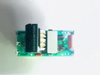
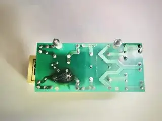
I am repairing an ultrasonic cleaner with a faulty circuit board. It has a blown out diode and capacitor that needs to be replaced. The board, however, has me curious and confused as to its function. I drew out the schemtic to the best of my abilities.
The large coil is a common mode choke according to its datasheet. It’s intended for filtering out high frequency noise, which is makes sense. There other boards drive the ultrasonic transducers at around 40 KHZ which may create interference.

The choke, diode and capacitor, however, appear to be stages in an AC to DC conversion. The choke is center tapped and rectified using only two diodes. This puzzles me since the choke’s datasheet only discusses its use for noise filtering.
Is the board both a DC filter and AC to DC converter? If so, shouldn’t the filtering be done after the AC to DC convention. Also, why would anyone want to use a choke instead of a transformer? I was under the impression that they were simple coils, not full blown transformers. Finally, not sure I drew it correctly, but what's the purpose of the two caps connected to ground?

