6

All of the images in this post are from Henry Ott's Book, Electromagnetic Compatibility 2009, and I would like some clarification on some things about them.

enter image description here enter image description here enter image description here

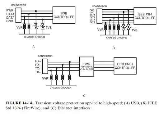
Figure 14-14 seem to be in conflict with Figure 3-24 and 15-15.

The circuit GND is connected through a TVS to chassis GND for 14-14, but in the other two, the circuit GND is connected directly to chassis GND. Is anyone able to reconcile this?

Also confusing me is 14-14a where circuit GND is connected to chassis GND via a TVS. As drawn, it doesn't look like it would protect from a transient across GND-PWR in either polarity until it is double the tolerable value. Similarly, if it were a unipolar circuit and unidirectional TVS diodes were used, it would not protect against a transient where GND becomes more positive than PWR. What's going on here?

enter image description here

UPDATE:

I found this diagram and text which helps clear things up: enter image description here
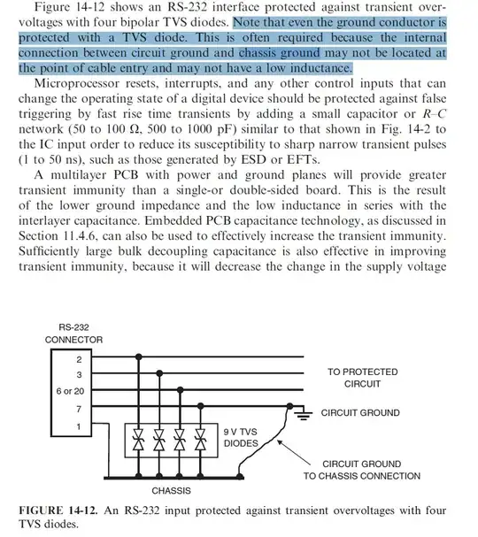
So I guess the wire tie between circuit ground and chassis ground is supposed to keep the two at equal potential over long periods of time but cannot be relied upon during ESD due to inductance. In which case the TVS diode tying circuit ground and chassis ground at the point of entry stops the circuit ground from straying too far from chassis ground during an ESD event. I assume pin 1 on the RS-232 connector here is the connector shell in direct contact with the chassis/enclosure.
DKNguyen
  • 54,733
  • 4
  • 67
  • 153
  • Hmmmm...I think there might be something that is being left unsaid about a transient and ESD event being different. I'm thinking that maybe transients come in over the lines and thus reference another line versus an ESD event which, presumably, is relative to the conductor with the largest free space capacitance in the system. This doesn't really reconcile how you would handle both though since two types of connections between chassis and circuit GND setups are mutually exclusive. – DKNguyen Jun 02 '20 at 20:28
  • ESD is usually Common Mode , not Differential Mode. So Chassis Gnd near entry point prevents dielectric current via PCB and conduction drop thru PCB ground – Tony Stewart EE75 Jun 02 '20 at 20:49
  • 1
    @TonyStewartSunnyskyguyEE75 Yeah. That. I'm a bit skeptical of how well a wire connecting to the PCB (upon which the TVS diodes are mounted) to the chassis actually performs though due to the inductance. It still doesn't really explain my question though. – DKNguyen Jun 02 '20 at 20:55
  • The sketches are rather sloppy and inductance matters and the shortest path matters. But still it is a common mode interference improved by raising the common-mode impedance. – Tony Stewart EE75 Jun 02 '20 at 23:39
  • The above meant raise Zcm but keep Zdm low and balanced. Then SNR and CMRR from AM-CW and impulse transients e.g. ESD improves and Shunt clamps attenuate better, – Tony Stewart EE75 Jun 03 '20 at 00:19
  • @VoltageSpike I have edited it to make it more clear. – DKNguyen Oct 07 '20 at 04:24
  • @DKNguyen Thanks – Voltage Spike Oct 09 '20 at 00:32

2 Answers2

1

Looking at figure 14-14A, I think there must be additional unidirectional TVS from GND to PWR, and probably a ferrite. The data lines typically get a small CM choke, sometimes series R (often built into chip however), and low-capacitance TVS diodes for hi-speed signal lines that are available now.

Pete W
  • 1,207
  • 1
  • 5
  • 12
0

Figure 14-14 seem to be in conflict with Figure 3-24 and 15-15.

How so? I don't see any difference between them.

EDIT!:

There was a typo in the original question. This is the new answer in response to the corrected question;

The circuit GND is connected through a TVS to chassis GND for 14-14, but in the other two, the circuit GND is connected directly to chassis GND. Is anyone able to reconcile this?

How do I reconcile that? Easy!

The author just meant to show the situation in which the TVS shorts due to a transient event. The two latter drawings are meant to show the current path, and as such do not show the actual TVS diode used to create the short in the case of a transient, in other words they are simplified depictions, that's all.

The circuit GND is connected through a TVS to chassis GND for 14-14, but in the other two, the circuit GND is connected to chassis GND through a TVS diode.

What? I think there was a typo? or am I misunderstanding something?

You say the exact same thing twice;

The circuit GND is connected through a TVS to chassis GND

And;

the circuit GND is connected to chassis GND through a TVS diode

What am I not getting? those two statements seem identical to me..

Also confusing me is 14-14a where circuit GND is connected to chassis GND via a TVS. As drawn, it doesn't look like it would protect from a transient across GND-PWR in either polarity until it is double the tolerable value.

Sure it needs to be double the breakdown voltage of one tvs before it protects against transients between pwr and gnd, this is most likely intended. Think of it like this; where does the transient come from in the first place? it is likely to be esd caused by a human touching the connector, in which case it will be common mode and will not occur differentially between pwr and gnd.

Similarly, if it were a unipolar circuit and unidirectional TVS diodes were used, it would not protect against a transient where GND becomes more positive than PWR. What's going on here?

Yes it would.

TVS diodes are conducting in the forward direction.

Vinzent
  • 2,233
  • 5
  • 18
  • Fixed. That was a typo. In response to "Yes It would" If you apply a negative voltage to PWR relative to the circuit GND, the diodes won't not turn on in time to short out the PWR and GND pins in the connector such that the the GND pin has not significantly have higher potential than the PWR pin. – DKNguyen Jun 02 '20 at 21:31
  • @DKNguyen "If you apply a negative voltage to PWR relative to the circuit GND, the diodes won't not turn on in time to short out the PWR and GND pins in the connector"... What in the world makes you say that???. You need to back that up with a reason why you don't think it would switch on in time.. Btw. I still see the exact same statement in your question. – Vinzent Jun 02 '20 at 21:34
  • @Viznent Forgot to click the save button. I don't really understand what there is to get. If both PWR and GND pins have a unidirectional TVS to the chassis GND, then that's the same as having one bidirectional TVS between PWR and GND pins (running through the chassis GND). So if a negative voltage is applied to PWR, the diode conducts when PWR > GND +Vr and GND > PWR + Vr. It would not conduct when GND > Vf would fry the something as if you connected something in reverse polarity. – DKNguyen Jun 02 '20 at 21:36
  • @DKNguyen Okay now I understand what you mean.. Yes you are right in that case it would not protect, but this is a completely hypothetical case, He doesn't show using a uni-directional tvs in any of the drawings, besides as I also said the purpose is not to protect against differential transients between pwr/gnd, but only common mode transients caused by f.eks. esd from a human touching the connector.. – Vinzent Jun 02 '20 at 21:42
  • I added a diagram. But being worried about common mode transients would explain why the TVS is connected to the chassis ground instead of directly. However, I am having trouble seeing the benefit of connecting the cct GND to chassis GND through a TVS instead of connecting directly connecting circuit GND. Like, I sort of get it but at the same time it seems that it would mutually exclude any measure to protect against negative transients coming in on PWR-GND. – DKNguyen Jun 02 '20 at 21:48
  • Well not ANY measures. So much as it would require yet another uni TVS directly across PWR-GND pins to clamp it. Is only ESD supposed to be shunted to the chassis? And it's not appropriate for signal transients? The book wasn't very clear to me on that point. Also, it still is muddled with how the Figure 3-24 explicitly seem to just directly connect cct GND to chassis GND. – DKNguyen Jun 02 '20 at 21:49
  • 1
    The purpose of all this is only to short common mode esd to chassis gnd, this is the most common approach. transients between pwr/gnd and signal pins is not what is handled in this example. And he doesn't explicitly show them connected directly, he shows the current path.. That is obvious to me at least. – Vinzent Jun 02 '20 at 22:07
  • How is breakdown for the TVS diodes chosen then if the circuit GND (and the circuit itself) just floats above the chassis GND? It seems like it could also be anything in that case but that doesn't feel right. – DKNguyen Jun 02 '20 at 23:15
  • 1
    @DKNguyen Yes it can indeed be "anything" you need to decide the breakdown voltage of the TVS depending on your required isolation voltage between circuit gnd and chassis gnd.. often your system will be required to have a certain amount of isolation between the circuit and chassis, such as if you are designing an ac-dc power supply or related equipment. – Vinzent Jun 03 '20 at 00:21