

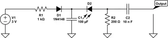
Hello I tried to simulate this circuit in Pspice or Hspice to generate sawtooth wave but I didn't get any result my Hspice code is shown below
[![sawtooth generator [2]](../../images/3806923873.webp)
Hello I tried to simulate this circuit in Pspice or Hspice to generate sawtooth wave but I didn't get any result my Hspice code is shown below
[
You have the option of including UIC on the .TRAN card if you don't want the Spice program to perform an "initial transient solution" step (so-called "ITS") to find the DC solution at \$t=0\$. If you don't use UIC, then Spice will proceed with the ITS step and this will set the initial conditions for the energy storage devices before it starts performing the transient step. On the other hand, when you use UIC, then the initial value of every single energy storage (voltage and current) device is treated as zero, except for those which are explicitly provided using the .IC card.
However, I'd like to use this opportunity to illustrate a more managed design. Sometimes, it helps to see them. The following circuit shows such a design:
simulate this circuit – Schematic created using CircuitLab
I've changed everything, basically. The current source has been replaced with a more manageable design topology. You can find much more on the topic here, if interested. But it's a better arrangement. Also, the "SCR" has been replaced with a much better and more consistent (managed) SCR behavior, including positive feedback through \$C_2\$ and \$R_7\$ to lock in the event in a reliable fashion. \$D_1\$ replaces a diode-connected BJT, with very different saturation current and emission coefficients, and forms up with \$Q_5\$ to create a current mirror with a current gain very much less than 1 (about 0.01 or less.) This is really all that is needed to drive \$Q_4\$. \$Q_3\$ is the voltage trigger for the SCR.
I've leave it there, but it's worth seeing what it takes to build something that copes with the vagaries of discrete part and temperature variations.
I've just placed all this into LTspice, today. Here are the results of a run:

The current source is about \$3.6\:\mu\text{A}\$ (\$Q_2\$'s \$V_\text{BE}\$ is about \$540\:\text{mV}\$.)
I had originally guessed that \$Q_3\$ would trigger at about \$V_\text{BE}\approx 500\:\text{mV}\$ and that \$D_2\$ would have about \$200\:\text{mV}\$ across it at the time. So this worked out to a trigger voltage of about \$3.5\:\text{V}\$. As it appears, it's closer to about \$2.9\:\text{V}\$.
But I'd call it "close enough."
Try to set an initial condition on a node. For example, you can set v(3) to be 0 by using the following line in your HSPICE test bench:
.IC v(3)=0
Your design is an example of a self-oscillating circuit which does require an initial condition to be set on at least one oscillating node. Another example would be a ring oscillator.
Oh, I see that @vtolentino beat me to it :-)
It seems to work fine in LTSpice:

The problem with your simulation seems to be the duration of the transient simulation. Increase it to at least a few 10s of miliseconds, as the capacitor requires some time to be charged and used to turn on the NPN transistor.