0

I'm helping a student at our art academy with an interesting project. She is building an array of peltier elements (let's say 25 to start with). She wants to control them individually using PWM and be able to switch the polarity on them every now and then.

We are aware this is a terrible idea in terms of thermal stress and the life expectancy of the elements, but we'd like to try it anyway for the sake of this project.

We could do it with an H-bridge for each one of the elements, but that would take a lot of work and components. I was thinking that we might be able to simplify it. Would it be possible to use four relays to reverse polarity on the power supply side, and then connect the peltier elements with optocouplers or something to do the pulse width modulation? That way, for each heating element we only need one component (which we open and close from an Arduino with a shift register), instead of a whole H-bridge module or four mosfets for each.

Which component would be a good fit if we want to send 12V @ 1 amps (peak 3 amps) through it? At first I thought a MOSFET like IRLZ44N would work, but they only work in one direction I think, with the source connected to ground. Would something like the TLP175A enable us to PWM the elements even when the direction of the current reverses?

Thanks for any advice!

EDIT

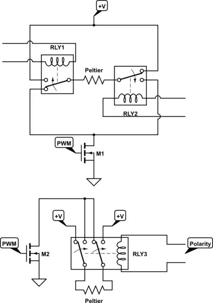
So I was thinking of something like this: enter image description here

But this has the problem that the MOSFETS will not work with the current in both directions. So I was thinking there would be an alternative component that would.

Tjaap
  • 3
  • 2
  • 1
    Please post a schematic of your proposed design, so that we can better assist you. – Aaron May 21 '20 at 15:38
  • @DKNguyen Thanks for your answer. No I didn't mean for the relays to be PWM'd, just the elements. So the relays switch the polarity every minute or so, and in the meantime the Peltier elements are PWM'd to let each have its own variable average voltage. – Tjaap May 21 '20 at 15:56
  • @Aaron Yes, I will try my hand at a schematic later on, thanks. – Tjaap May 21 '20 at 15:57
  • An h-bridge works... make sure you properly deal with the thermally induced voltage of the peliters – Voltage Spike May 21 '20 at 21:48

1 Answers1

3

You may connect relay coils in parallel or series for polarity control as long as you connect relay main contacts as opposite (normally open on one and normally closed on the other).

You can also just use one DPDT relay instead of two SPDT relays.

schematic

simulate this circuit – Schematic created using CircuitLab

DKNguyen
  • 54,733
  • 4
  • 67
  • 153
  • One double pole double throw (DPDT) relay will do, as long as you have the PWM FET to turn the power off. – Peter Bennett May 21 '20 at 15:51
  • 1
    @PeterBennett Yes, but uglier to draw so that it resembles an h-bridge and less selection. – DKNguyen May 21 '20 at 15:53
  • @DKNguyen These are very helpful, thank you! Is there an obvious choice for a DPDT relay we should use, one that can handle 12V/3A and preferably TO-220/DIP and low cost? – Tjaap May 21 '20 at 17:23
  • @DKNguyen Now that I'm starting to understand... :-) couldn't we switch polarity near the power source, for all elements at once? That would save us a lot of relays. I'll draw up a schematic of what I had in mind. – Tjaap May 21 '20 at 17:29
  • @Tjaap Relays are not polarity sensitive have have control terminals completely independent of the main terminals (two control, two main). MOSFETs are share a terminal between both control and main, are polarity sensitive, and can only block current in one direction. – DKNguyen May 21 '20 at 17:44
  • @Tjaap That means you putting a MOSFET in a position where current can flow through it both ways results in massively increased complexity (you know need two back-to-back MOSFETs, one to block current in each direction) and the sharing of control and power terminal makes your control more difficult if the MOSFET is not in a position where that shared terminal is fixed to a know voltage (i.e. GND) so that you can drive it with a simple voltage (otherwise you need a floating voltage). – DKNguyen May 21 '20 at 17:51
  • MOSFET is controlled by the voltage DIFFERENCE between gate & source terminals. NOT just the voltage at the gate (implied to be relative to GND) since voltage is always between two points. Not fixing the source to a know voltage but driving the gate relative to a fixed voltage will cause the source pin voltage to rise as the MOSFET conducts and current flows through the load which will act to inhibit the MOSFET from turning on further resulting in a half-on/off state. – DKNguyen May 21 '20 at 18:00
  • Optos when used properly can provide a floating voltage, but aren't that great for PWM current drive requirements depending on your frequency, and you still have your MOSFET two-way blocking problem so that's still increases your complexity. So you must decide whether you want more relays or more MOSFETs+drive circuitry. More relays will require less knowledge. – DKNguyen May 21 '20 at 18:02
  • Aah yes the speed would be important too of course. Ok this makes a lot more sense now, thank you very much! I think I will propose dropping the requirement to reverse polarity, in order to reduce cost and complexity :-) – Tjaap May 21 '20 at 18:06
  • @Tjaap Do the peltiers need independently controlled polarity or PWM? Why can't you just group them all under the same H-bridge? Is switching polarity only optional? Between switching polarity and PWM, polarity is usually the one an application cannot live without if it is required. – DKNguyen May 21 '20 at 18:09
  • @DKNguyen I'd rather not divulge the specifics of my student's project, I don't know if she would mind. But yes, in this case the variable power on each of the individual panels is more important than switching the polarity. But it's her artwork, so her call :-) Thanks again! – Tjaap May 21 '20 at 19:04