Modulo 5 Magic
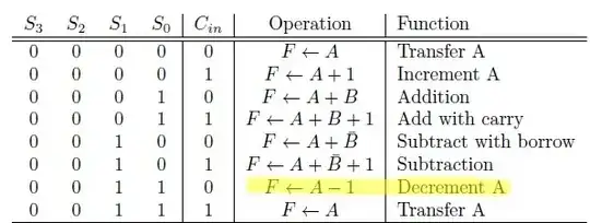
Suppose you had some magic logic block which did the following:
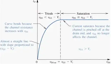
Above, if \$x=A_3\dots A_0\$, then \$S_3=\lfloor\frac{x}{5}\rfloor\$ and \$S_2\dots S_0=x-5\cdot S_3 = x \mod 5\$.
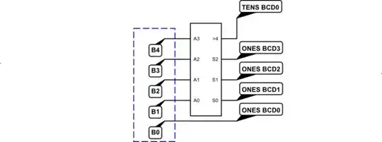
Now look at what happens when we apply this magic logic block:
simulate this circuit – Schematic created using CircuitLab
The 4-bit value, \$y=B_3\dots B_0\$ where \$0\le y\le 15\$, is converted to one BCD digit, plus a "carry" into the next higher BCD digit. This happens because the magic logic block as applied only to the upper 3 bits (which cannot exceed 7), \$y^{'}=\lfloor\frac{y}{2}\rfloor\$, and performs the following mathematics: \$S_3=\lfloor \frac{y^{'}}{5}\rfloor\$ and \$S_2\dots S_0=y^{'}-5\cdot S_3\$ which is the same thing as having performed \$S_3=\lfloor \frac{y}{10}\rfloor\$ and \$S_2\dots S_0=y-10\cdot S_3\$. In short, we've performed a divide-by-10 operation and a modulo-10 operation. Which is just the kind of thing we need to do in order to convert binary into BCD.
Generalizing
Note that in the above diagram, I set \$A_3=0\$. This ensured at the \$A_3\dots A_0\$ input doesn't exceed a maximum BCD value of 9. With only three bits, we can be certain of that. But if we now expanded the diagram to something like this:
simulate this circuit
We run into a problem because it is possible for \$B_4\dots B_1\ge 10\$ and this would violate the requirement that the 4-bit input into the magic block is already in BCD format.
This can be fixed:
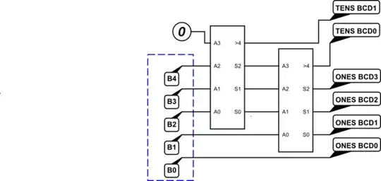
simulate this circuit
Note that I've just once-again assured that the left-most modulo-5 (it's not magic, anymore) block is guaranteed to have a BCD input (since we set its upper-most input bit to zero.) This left-most modulo-5 unit's lower \$S_2\dots S_0\$ output cannot be more than 4. So even now combined \$B_1\$, you can see that the right-most modulo-5 unit's input will still be in BCD format. So no violation there.
Note also that the input, in binary, can be from 0 to 31. And that we now have two bits for the upper BCD digit. Just enough to cover the need!! Nice.
Continuing the Generalization
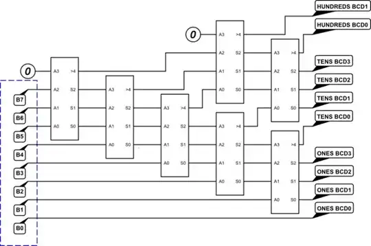
This whole idea just continues on. Or, at least, it might seem so. Let's extend this idea to handle your 7-bit input:
simulate this circuit
Will this work? No. It won't. One obvious reason is that we don't have a HUNDREDS BCD digit and we know that you need one. So there's something wrong, already.
But the somewhat more subtle reason is that we've brought out each of the carry-outs from each modulo-5 block and formed a TENS BCD digit. But there might be a carry-out from all of the blocks (or some combination that doesn't make a BCD digit.) In fact, we should expect a carry-out from the TENS so that we do get a bit provided into the HUNDREDS BCD digit.
There's a way to fix this, though:
simulate this circuit
And that, in fact, will work fine.
Summary
I've not disclosed the logic required for the modulo-5 block. But as I have provided you with the table, this should not be a difficult puzzle for you. It will need a few logic gates to map \$A_3\dots A_0\$ to \$S_3\dots S_0\$.
If you have trouble with that block, feel free to ask a different question about it. But I suspect you can work it out.
Note
See BCD K-Maps for an earlier post of mine on a related question. Also see this by qwr on another still earlier question on the double-dabble algorithm.
Appendix
I've decided, a week later, to expand on the above and make this a broader answer that may help others.
The above example can be expanded to 8 bits in the following way:
simulate this circuit
I think this should provide sufficient information to allow expansion to any number of bits and decimal digits.
