5

I wish to power my Raspberry Pi 4 from a 12V DC battery and to do that I purchased these two products:

I tested the regulator and it works beautifully – by powering the Pi via its GPIO power rail pins 4 and 6 – it sustained a ~2.4A load with no problems at 4.98-4.99V.

For the life of me I don't understand what I'm doing wrong on the USB Type-C cable part, I get ~4.8V and dropping hard when increasing load when I try to attach the USB connector. Steps taken so far:

  • removed the 5.11kΩ pull-down resistors on CC
  • attached a 10kΩ pull-up on each of the two CC ports (supposedly advertising a 3A capable source if I read the USB Spec correctly).
  • shorted D- and D+ together

I tested the USB Type C cable with an AC adapter and a native DC 5V powerbank so that's not the culprit.

Do I really need a Power Delivery controller or am I missing something?

PS: this is the consumer's (Raspberry Pi's schematic), it seems to correctly be wired as a sink with 5.11kΩ pull-down: raspberry pi power diagram

PPS: soldering job between regulator and usb-c breakout soldering job between regulator and usb-c breakout

tXK
  • 51
  • 7
  • 1
    It might be helpful to know more about the wiring between your regulator, USB breakout, and Pi. I've personally had similar experiences only to realize that the wire I was using between devices was thinner gauge than I thought. A 0.2V drop could be expected if you are using (as I did) crappy 26 AWG "jumper" wires for testing. – JYelton May 15 '20 at 21:05
  • I don’t think it’s due to the wires, I did my best to rule them out: the USB cable was tested with a power bank and an Anker PD AC charger. Everything up to the regulator is fine - because it works well when plugging it into the GPIO pins. Only the cable connecting the regulator to the USB breakout would not be 100% tested but that is way thicker than what I used to test the regulator alone.. – tXK May 16 '20 at 05:17
  • 1
    What are you using the USB-C connector for? If you are just powering the RPi isn't doesn't seem you need it. – nate May 18 '20 at 19:10
  • 1
    "when I try to attach the USB connector" - which "USB connector"? Attach to what? Could you just draw an exact schematics of what you are connecting to what, using which cable, and where do you see the voltage drop. – Ale..chenski May 18 '20 at 19:42
  • @nate I do want to power it "normally", via USB-C and use the GPIO pins for other purposes. – tXK May 19 '20 at 06:17
  • @Ale..chenski USB connector = Pololu USB 2.0 Type-C Connector Breakout Board. When I attach it to my regulator and USB-C cable. I'm not sure I can draw a scheme but the problem goes like this: DC12V -> Regulator (12V->5V) -> USB-C Breakout (Female) -> USB-C Cable -> Pi 4. The problem seems to be at either at the USB-C breakout or in the Pi's USB-C controllers.. or I didn't understood the USB-C protocol :) I've used soldering to connect the breakout to the regulator. – tXK May 19 '20 at 06:17
  • @Ale..chenski I'm using an Anker USB-C - USB-C cable that I successfully tested with an AC adapter and with an 5V power bank. The voltage drop was measured both by the Raspbbery Pi (its power good led was turning off) and I also used a multimeter on pins 4 and 6 from the GPIO power rail. While these voltage drops were happening on the PI, on the regulator my measurements showed the voltage was stable - 4.99V. I think the Pi simply doesn't draw enough power when using the breakout but I don't know the reason for it. – tXK May 19 '20 at 06:25
  • @tXK Have you measured the power consumption of the Raspberry at start up and normal operating condition? – vtolentino May 19 '20 at 07:20
  • @vtolentino yes, at maximum it drew about 2.4A (with the configs that.. worked :D). – tXK May 19 '20 at 08:24
  • @tXK what about the minimum current? At any moment does your Raspberry draw an insignificant current? – vtolentino May 19 '20 at 09:02
  • @vtolentino not sure about that, why would it be important though ? – tXK May 19 '20 at 13:22
  • @tXK Most of the power banks have a power saving feature which shuts down the output voltage if the current drawn from it is too small. It prevents it from self discharging. Is the output voltage always available at the Raspberry end? – vtolentino May 19 '20 at 13:27
  • so the powerbank works fine, it’s the circuit with the usb-c breakout that doesn’t. the power draw when idle is somewhere around 5V 0.75A – tXK May 19 '20 at 15:25
  • If the cable is tested good, and the converter outputs solid +5 V, it looks like your "breakout Type-C board" can't handle 2 A of current, maybe some cheap bootleg connector is used with weak contact rating or poor metal plating. Check inside if all 4 contacts are present in the connector, 4 for GND, and 4 for VBUS. Also, you don't need to short D+ with D-, it is from a different standard. – Ale..chenski May 19 '20 at 22:14
  • Also, could you show a picture of your soldering job? – Ale..chenski May 19 '20 at 22:17
  • @Ale..chenski attached the soldering job, before removing the 5.11k and adding the 10k ones – tXK May 20 '20 at 09:28

1 Answers1

1

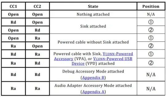
Apparently the problem you are facing has been reported before, and it lies on the pull-down resistors of the Raspberry 4. In short, there should be independent resistors for the CC1 and CC2 lines in order to detect the operating mode according to the following:

table

schematic

Quoting the prossible problem description:

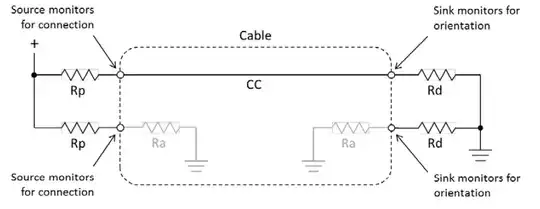
In the correct operation the charger will sense the Rd resistor (Or Rd Ra cobination) and turn on the power. The problem comes when an active cable which presents an Ra at both ends is used. On the source side one CC pin will be connected to the Ra resistor in the cable and the other to the CC line to the Pi. The Pi has connected both lines together so presents the combination of the Ra at the pi end of the cable and the Rd pulldown. Calculating the presented resistance assuming a average value of Ra still gives a value well within the Ra range (also note Ra resistances are permitted to go below 800 when cable electronics are drawing power so a resistance lower than 800 will also likely be detected as Ra).

$$R_{T}=R_a || R_b = 1k\Omega || 5k1\Omega=836\Omega$$

With effectively two Ra values presented to the Source end it will detect the Pi as an “Audio Adaptor Accessory”. These are analogue audio interfaces to allow for headphones to be connected to phones for example (although some phones use headphones/adaptors with inbuilt sound-cards which appear as USB devices). The audio adaptor accessory also allows the phone to be charged through the adaptor. This means the the device should not provide power on the Vbus pins which means no power for the Pi.

Possible solutions

Solution 1:

Assuming the issue you are having is caused by the problem discussed above, using a non e-marked cable (most USB-C phone charger cables are likely this type) rather than an e-marked cable (many laptop charger/thunderbolt cables and any 5A capable cable will be in this category) will allow for the pi to be powered. In addition using older chargers with A-C cables or micro B to C adaptors will also work if they provide enough power as these don’t require CC detection to provide power.

Solution 2(source):

Ultimately though the best solution in the long run will be for there to be a board revision for the pi 4 which adds the 2nd CC resistor and fixes the problem. If you want your USB Type-C devices to work correctly then you need to have two independent CC resistors. The simplest implementation of this is to use two 5.1k pull down resistors on the CC lines. This allows for detection by other devices when using a USB C-C cable. The USB 2.0 Data lines can both be connected together at the receptacle as only one pair will be populated in the connector. The power and ground lines will all want connecting to the appropriate power rails on your board. The Sideband pins and superspeed pins should be left unconnected in this configuration.

vtolentino
  • 3,529
  • 1
  • 7
  • 17
  • my source is "dumb", it doesn't detect anything as an audio device – there are just - and + plugs from a battery wired to those connectors, nothing else.. – tXK May 21 '20 at 12:08
  • @tXK Shouldn't your breakout board have pull up resistors instead of pull down ones? see the picture I added to my answer. – vtolentino May 21 '20 at 13:05
  • in the question above I mentioned that I removed the pull down 5.11k ones and replaced them with pull up 10k ones. – tXK May 21 '20 at 17:04
  • Did you try adding two independent pull-down resistors to the `CC1` and `CC2` lines? – vtolentino May 21 '20 at 19:03
  • tried that too, yes – tXK May 22 '20 at 06:31