0

enter image description here

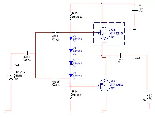
Above is a push pull Amplifier. As we all know the 8 ohm speaker is not receiving enough juice from the supply rails, in fact its only getting around 16 watts of power, how can we double that amount to make it like 40 watts. It appears that varying the resistors value has no effect. How can we make the speaker receive more current (we can make it absorb more current by lowering the speaker's impedance but let's say the impedance is fixed at 8 ohms).

vvavepacket
  • 2,473
  • 9
  • 38
  • 56
  • 2
    Why bipolar transistors rather than FETs? – pjc50 Nov 26 '12 at 13:04
  • im not that familiar to FETs – vvavepacket Nov 26 '12 at 13:07
  • 1
    The annoying clutter in your schematics is back, and you once again connected the scope-looking thing between input and output. The blocks with the green numbers are particulary bad since they sometimes seem to be short and other times measure voltage. You are also being sloppy with junction dots again. Trying to help you is apparently pointless since you won't fix things already brought up. – Olin Lathrop Nov 26 '12 at 14:30
  • @OlinLathrop, I believe that the scope isn't between the input and output but rather, the input and output are two separate inputs with, I assume, the ground implied. – Alfred Centauri Nov 26 '12 at 14:46
  • 3
    @Alfred: Ah, that could be I suppose. However, none of that clutter belongs in a schematic when you present it to others. Do what you want with a simulator for your own purposes, but clean it up before presenting it. That stuff makes it harder to see the underlying circuit, and you have to wonder how these blocks might be effecting it. The OP has been told this before, but for some reason is refusing to cooperate. – Olin Lathrop Nov 26 '12 at 14:58
  • 2
    @OlinLathrop, I agree and it is my opinion that the OP is close to wearing out his welcome here. – Alfred Centauri Nov 26 '12 at 15:21
  • 16W * 2 = 40W? LOL – dext0rb Nov 26 '12 at 15:34
  • 2
    The schematic is scarcely needed to understand the primary problem. – Chris Stratton Nov 26 '12 at 15:50
  • You are seeing unity gain; 17 Vpk sine wave is about 12 Vrms. (and 12 Vrms into 8 ohms is 18 W) – markrages Nov 26 '12 at 21:58
  • 1
    @OlinLathrop oscilloscope and other clutter has been remove really sorry. i now understand your point – vvavepacket Nov 26 '12 at 22:02
  • 1
    That's a lot better, but in the mean time you have gotten other answers and accepted one, so it's pointless to say more here. Keep the schematic clarity in mind for next time. By the way, switching to darlingtons is a little silly, especially without at least a little emitter resistance. There are better ways to use multiple transistors. – Olin Lathrop Nov 27 '12 at 13:28

4 Answers4

7

The amplifier shown is a pair of emitter-followers used to boost the current available to the load; it has less than unity voltage gain.

The only way to increase the power (voltage) to the speaker is to drive the input with a higher-voltage signal.

Dave Tweed
  • 168,369
  • 17
  • 228
  • 393
  • ok, lets say we cant increase any more the input voltage, any good substitute for the emitter followers? – vvavepacket Nov 26 '12 at 13:27
  • 2
    No, and this is why multi-stage amplifiers exist. The early stages provide voltage gain while the latter stages provide the current gain needed to drive low-impedance loads. – Dave Tweed Nov 26 '12 at 13:32
  • 1
    There are substitutes, but not really good substitutes (common emitter stage here has other problems; higher output impedance, more difficult biasing). Dave's right - another stage is simplest and best. –  Nov 26 '12 at 13:35
  • looks like i really need to increase Vcc. how about using a boost converter??? it will boost voltage but will not provide more than 1 A of current – vvavepacket Nov 26 '12 at 13:37
  • No, it's the *signal* voltage that's limiting the power to the speaker, not the supply voltage. With your existing 40V supply, you should be able to deliver a theoretical maximum (ignoring headroom) of 25W (sinewave, 14.14 Vrms) to an 8-ohm speaker. – Dave Tweed Nov 26 '12 at 14:03
6

You have asked what essentially boils down to the same thing previously, and peripherally worked over the same shrubbery here. There has been at least one alternative solution offered, perhaps more.

If there is a linguistic or cognitive challenge, then no comments. Otherwise, the Bridge-Tied-Load configuration remains one of the potential solutions to the issue. Also, it will certainly be simpler to implement than a boost circuit, given the circumstances.

Anindo Ghosh
  • 50,188
  • 8
  • 103
  • 200
4

As we all know the 8 ohm speaker is not receiving enough juice from the supply rails, in fact its only getting around 16 watts of power,

Of course it's only getting about 16W. To deliver 40W average power (with an undistorted sine wave) to the 8 ohm load, you must have almost 18VAC at the output of your amplifier. That's a little over 25Vpk or a little under 51Vpp. You can't do that with a 40V Vcc.

Since you loose some voltage across the base-emitter junctions and you'll want some headroom , the Vcc should be, say, 55V instead of 40.

And, of course, since the voltage gain is less than 1, your source voltage will need to be larger than 25Vpk.

Finally, your power supply must be capable of supplying the peak current and of sustaining the average power, the calculation of which I'll leave as an exercise for the OP.

Alfred Centauri
  • 26,502
  • 1
  • 25
  • 63
2

Everyone has overlooked that you are losing half of your "punch" in the series output capacitor. 1000 uF is 8 ohms at 20Hz which is where speakers can be seen to punch. Of course juice is a punch so I am not sure what band that belongs to. Maybe rock N roll but more "real" fruity sounding than "punch" ;)

(levity helps when questions get monotonic or repeat themselves.)

Tony Stewart EE75
  • 1
  • 3
  • 54
  • 182
  • Not only that, but the design will have serious crossover distortion, since the diode drops are just enough to bias it class B. And there isn't any shred of negative feedback which would mitigate the crossover distortion. Ideally we want negative feedback and a bit of juice to keep it AB. – Kaz Nov 27 '12 at 00:35