17

I have the doorbell button on my house wired into a GHI EMX dev board. The software evaluates the time of day and determines whether or not the doorbell should ring.

Side Note: This was implemented as a way to deal with ding-dong-ditch pranks that I was receiving.

This all works great except for one problem, the wire connected to the EMX board is around 50 feet (~15 meters) long and generates enough interference for the board to think that someone has pushed the button and thus my doorbell rings at random intervals throughout the day. Both my wife and my dog do not appreciate this (but the kids think it's great fun).

I've tried fixing the problem by following the advice found in this article and implementing the following circuit:
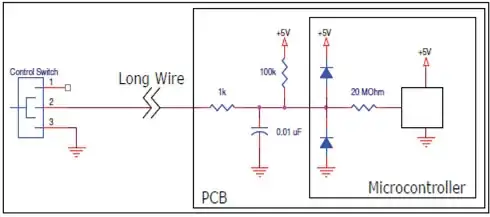
Low pass filter protection for an input

This didn't fix the problem, but I did find that putting a 3k resistor in the for 1k and replacing the .01uF capacitor with a 40uF worked a little better, but anything more than 3k causes a noticable delay when pressing the button before the bell rings. The difference for my circuit is that the board runs on 3.3V instead of 5V (which I assume makes the problem worse) and instead of connecting to ground the switch completes the circuit (i.e. two wires go between the microcontroller and switch).

The wire that runs between the switch and the microcontroller is standard doorbell wire which isn't shielded or twisted. Replacing the doorbell wire with shielded wire is, unfortunately, not an option since that would require that I tear drywall off.

I've looked at the following question here, but that seems to be dealing with a ADC which might be a little different from my problem. Any help would be much appreciated.

Update
After reading more of the documentation, it appears that although the microcontroller is powered by 3.3V it is 5V tolerant on it's I/O pins. I can adjust to a higher resistor value if I use 5V, but will this help anything?
Matt Ruwe
  • 1,957
  • 7
  • 23
  • 35
  • 1
    Add a security keypad to your doorbell. Only those who enter the correct four-digit code can ring it, any time of day. – Kaz Nov 27 '12 at 21:37

4 Answers4

16

What the schematic does not show is the huge common mode 60Hz hum and how the grounds are interconnected with proximity to AC lines & power line transients.

Your example is a good example of how not to interface long wires.

May I suggest in future;

  1. prefer twisted pair
  2. prefer balanced lines
  3. avoid high impedance inputs
  4. prefer matched impedances
  5. avoid excessive LPF ( long time constants)
  6. include RF cap to suppress transients.
  7. use ferrite beads (CM choke)
  8. avoid ground loop (ie. direct untapped connection to circuit)
  9. use contact wetting circuit ( correct polarity 10uF cap across contacts that are not gold plated)
  10. prefer coax for very harsh EMI environment.

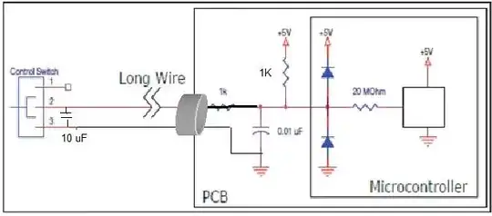
Since many options are not avail. Do these;

  • remove big cap on board and move to remote switch contacts. (must)
  • remove 3K(1k) series resistor and add ferrite CM sleeve or similar
  • add small RF cap on board across input. e.g. 0.001~0.01uF or any low inductance type.
  • Replace 100K with 1k~10K.
  • add large ferrite beads with multiple turns to both wires. (CM filter)

With this solution, the switch circuit impedance will low impedance on closure and low impedance with elect-cap across switch when open. CM hum will be absorbed and differential RF noise is suppressed. enter image description here

-pullup to same supply voltage as uC with good RF cap across chip.

Tony Stewart EE75
  • 1
  • 3
  • 54
  • 182
  • I'll have to find a ferrit CM sleeve but otherwise this looks very doable. Do you think this will work: http://www.digikey.com/product-detail/en/KR50TA251512B1/P11400-ND/409505. Thank you! – Matt Ruwe Nov 26 '12 at 02:48
  • will work without, but added insurance for stray RF bursts. These are better.. http://www.digikey.com/product-detail/en/FB73-287-RC/M8708-ND/775247 get a dozen or more for future use. – Tony Stewart EE75 Nov 26 '12 at 03:01
  • read wrong ID http://www.digikey.com/product-detail/en/35T0231-30P/240-2586-ND/1587459 above are too small. Yours will be OK too but becoming obsolete. – Tony Stewart EE75 Nov 26 '12 at 03:09
  • Thank you. Couple of other questions. In a residential environment like mine, what should I tie the common ground to? A nearby electrical ground or plumbing? – Matt Ruwe Nov 26 '12 at 12:45
  • nearby electrical outlet or computer case ground connected to outlet is fine. Long wires add too much inductance >1m. – Tony Stewart EE75 Nov 27 '12 at 14:09
9

A simple solution may be to leave the doorbell system how it was before you started this project and just use the micro controller to kill power to the door bell speaker with a relay when you don't want to hear the bell.

Update

I'm not very familiar with doorbell systems (other than a quick google) so the following assumes you have at least two conductors running from your MCU to the switch.

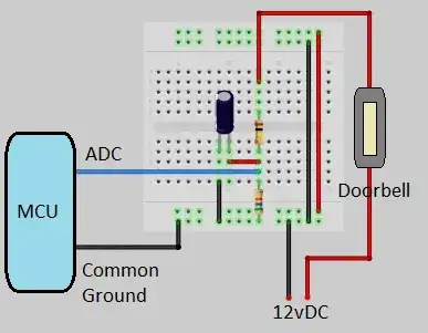
The GHI EMX board you have has a 10 bit ADC so you could send 12vDc (or more) to the doorbell and use a simple voltage divider so that the voltage to the MCU isn't over it's 5 volt max. Then on the software side all you would do is read the ADC and if the value is > 1000 (you may have to play around with this number, and 1023 is the max on a 10 bit ADC) then the doorbell has been pressed.

It would look something like this (try not to be overwhelmed by my awesome graphic editing skills):

enter image description here

Another option that's kind of similar is to use a schmitt trigger with a higher input voltage. But this would require extra parts and is more effort than the ADC option.

Edit

Chris Stratton's answer made a good point about the current flow. If you change the 100k pull up resistor to a ~220ohm one that may do the trick.

Garrett Fogerlie
  • 4,958
  • 1
  • 22
  • 47
  • 1
    Not a bad idea, but it takes some of the fun away from the concept. I would still like to know when the switch is pressed after hours so I can flip the front lights of the house on and give the pranksters a little of their own medicine. – Matt Ruwe Nov 26 '12 at 02:21
  • maybe the sound a distant police siren coming closer with a taser on the switch. – Tony Stewart EE75 Nov 26 '12 at 02:36
  • 1
    My favorite suggestion was from a friend who had the idea to use an electric match connected with some fireworks that would be set off when the button is pressed. =) In the end that idea was just too dangerous, though. – Matt Ruwe Nov 26 '12 at 02:51
  • @Matt see my update for another solution. Instead of fireworks, I once used a siren and a strobe light cause kids were smoking on the side of my house. I caught it on video too, which made it that much better! – Garrett Fogerlie Nov 27 '12 at 08:53
7

There is actually a very simple solution to this problem.

The key to understanding this solution is to think about why a plain electro-mechanical doorbell does not ring due to similar interference. The answer of course is that it requires the actual ring power to flow through the closed circuit - interference will not couple enough power into the open circuit to falsely ring.

You can create a similar situation by using a low-value pullup resistor, with the doorbell button connecting to ground. A hundred ohms of resistance would mean that around a 25 milliamps of current would have to flow before the microcontroller input is pulled low enough to read as a "0". Long haul serial communication is often done with a 20 mA current, so 25 mA should be enough, but you can easily adjust up or down.

You can further reject interference by having software on the microcontroller which requires the button to be maintained closed - with no gaps - for a 100 mS or so before it will be recognized as a valid ring.

One could argue that this method is wasting power, however the power is only consumed during the time when the buzzer is held down. The resistor does need to have the power handling (thermal) capacity for the possibility of the button jamming permanently closed, but that would not be the ordinary case for figuring power consumption.

Chris Stratton
  • 33,282
  • 3
  • 43
  • 89
  • unless you use 10% or rated current on non-Au contact metallic switches, it will eventually fail starting intermittent with logic level currents. That is why the low ESR cap across (pref film cap) is essential to reduce oxiation with low ESR high current dump across contacts. – Tony Stewart EE75 Nov 30 '12 at 16:06
  • @Richman - eventual failure is possible, yes - it is when using an electromechanical buzzer as well. One could increase the current on the theory that might help or try your pulse capacitor idea. Some designs of doorbell buttons may implicitly have some sliding contact as the leaves depress, which would help a lot. I have my suspicion that an easily rectified failure after a number of years would not be a showstopper for a convenience device someone builds for their own house. On a practical level, it's useful if the person at the door can at least faintly hear the bell. – Chris Stratton Nov 30 '12 at 16:24
0

The 15 meters cable is acting like an antenna. You need to use a feedthru capacitor (for example W2F11A4708AT1F) in order to filter the RF interference.

embedded.kyle
  • 8,411
  • 2
  • 26
  • 44
Aldanajaramillo
  • 388
  • 1
  • 8